Rear panel connections – Extron Electronics MLA VC10 Plus User Guide User Manual
Page 10
Rear Panel Connections
RS-232
RELAY
V-DC
R
Tx Rx
G
G
G
V
C
NO
NC
C
POWER
0.3A MAX
12V
CONTROL
OUTPUT
REMOTE
f g
j
i
h
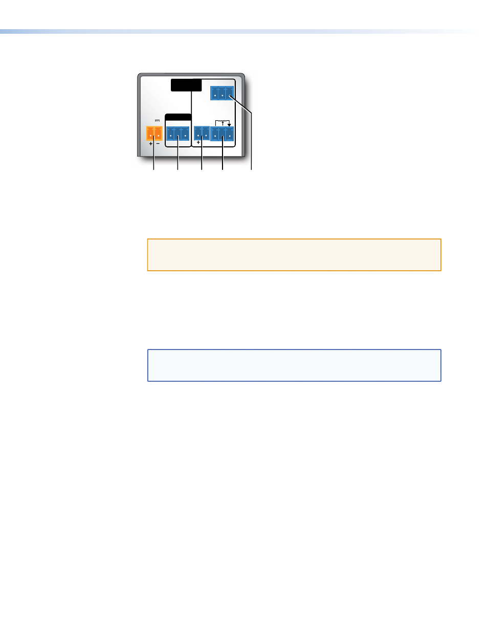
Figure 3.
MLA VC10 Plus Rear Panel
f
Power — Connect a 12 VDC power supply to this two pole captive screw connector.
The MLA VC10 Plus can be wired to share the power supply with other products
(see “
Sharing a Power Supply with an Extron Controller
” page 12 for more
information). The Extron power supply (part number 70-775-01) is optional.
ATTENTION: Before connecting power, see “
on page 11 for important information about using the power
supply.
g
RS-232 control — The MLA VC10 Plus is controlled by RS-232 instructions from
a MediaLink, IP Link, or third-party controller or a PC. Connect the RS-232 control
cables, from the controller or PC to this 3.5 mm, 3-pole captive screw connector.
h
V-DC control — To use variable DC voltage output to control the volume of an
amplifier, connect the MLA VC10 Plus to the amplifier using this 3.5 mm, 2-pole
captive screw connector.
NOTES: The amplifier audio level can be controlled by either voltage or by
resistance but, at any time, only one can be active, see “
SIS commands on page 35.
i
Resistance Control (default setting) — To use the digital potentiometer to control
an amplifier, connect the MLA VC10 Plus to the amplifier using this 3.5 mm, 3-pole
captive screw connector.
j
Relay Switch — To use the relay for mute control or other purposes, determine
whether the amplifier needs a Normally Closed (NC) or Normally Open (NO) relay.
Connect the common (C) pole and either the NO or the NC pole of the captive screw
connector to the amplifier.
MLA VC10 Plus • Panels and Connections
4