Remote connection, Installation, cont’d, Caution – Extron Electronics MAV 44_48_84_88 Series User Guide User Manual
Page 22
Installation, cont’d
MAV 44 / 48 / 84 / 88 Matrix Switchers • Installation
2-6
7
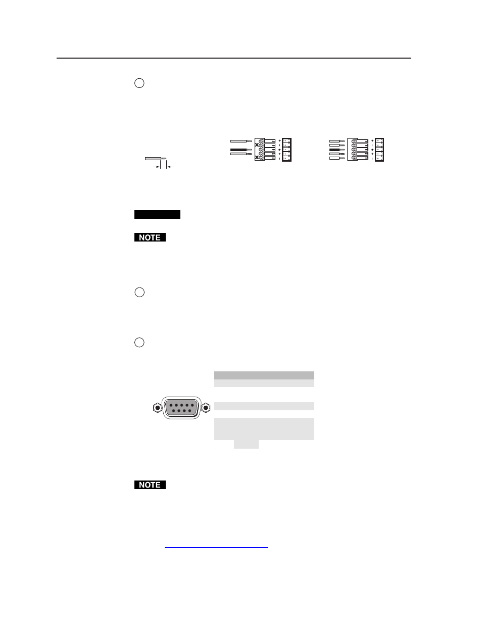
Balanced or unbalanced audio output connectors (captive screw audio
connector [A] models only) —
These 3.5 mm, 5-pole captive screw connectors
output the selected unamplified, line level audio. Connect audio devices,
such as an audio amplifier or powered speakers to these connectors. See
figure 2-6 to properly wire an output connector.
Do not tin the wires!
Unbalanced Stereo Output
Tip
NO GROUND HERE.
Sleeve(s)
Ground
Tip
NO GROUND HERE.
Balanced Stereo Output
Tip
Ring
Tip
Ring
LR
LR
Left
Right
Left
Right
3/16” (5 mm) Max.
Figure 2-6 — Captive screw connector wiring for audio output
CAUTION
Connect the sleeve to ground (Gnd). Connecting the sleeve to a negative
(-) terminal will damage the audio output circuits.
The length of exposed wires is critical. The ideal length is 3/16” (5 mm).
• If the stripped section of wire is longer than 3/16”, the exposed wires may
touch, causing a short circuit between them.
• If the stripped section of wire is shorter than 3/16”, wires can be easily
pulled out even if tightly fastened by the captive screws.
8
RCA connector audio output (RCA connector audio [A RCA] models only) —
The switcher has a pair (left and right) of RCA connectors for each unbalanced
stereo audio output (figure 2-5).
Remote connection
9
RS-232 connector —
Connect a host device, such as a computer or control
system, to the switcher via this 9-pin D connector (figure 2-7) for remote
control of the switcher.
Pin
RS-232
Function
1
—
Not used
2
TX
Transmit data
3
RX
Receive data
4
—
Not used
5
Gnd
Signal ground
6
—
Not used
Not used
Not used
7
—
8
—
—
5
1
9
6
Female
Hardwired IR input
9
Figure 2-7 — RS-232 port pin assignment
The cable used to connect the RS-232 port to a computer or control system
may need to be modified by removing pins or cutting wires. If you encounter
problems while operating under RS-232 control (the switcher may hang up),
pins 1, 4, 6, 7, 8, and 9 may need to be disconnected. Either cut the wire to
pins 1, 4, and 6 through 9 in a hard-shelled connector or remove pins 1, 4, and
6 through 9 from a molded plug.
See chapter 4, “Remote Operation”, for definitions of the SIS commands and
details on how to install and use the control software.