Extron Electronics MAV 44_48_84_88 Series User Guide User Manual
Page 21
2-5
MAV 44 / 48 / 84 / 88 Matrix Switchers • Installation
Audio input and output connections (audio/video models)
The audio level for each input can be individually set, via the front panel or RS-232,
to ensure that the level on the output does not vary from input to input. See
chapter 3, “Operation”, and chapter 4, “Remote Operation” for details.
By default, the audio follows the video switch. Audio breakaway, which is
commanded via the front panel, under RS-232 control via the SIS or Windows-
based control program, or optional IR 501 control, allows you to select from any
one of the audio input sources. For details, see chapter 3, “Operation”, and
chapter 4, “Remote Operation”, and refer to the IR 501 Small Matrix IR Remote
Control User’s Guide.
5
Balanced or unbalanced audio input connections (captive screw audio
connector [A] models only) —
Each input has a 3.5 mm, 5-pole captive screw
connector for balanced or unbalanced stereo audio input. Connectors are
included with each MAV AV captive screw connector switcher, but you must
supply the audio cable. See figure 2-4 to wire a connector for the appropriate
input type and impedance level. High impedance is generally over 5 k ohms.
Figure 2-4 shows two methods of wiring the captive screw audio connectors for
input and figure 2-6 shows two methods of wiring the connectors for output.
A mono audio connector consists of the tip and sleeve. A stereo audio
connector consists of the tip, ring, and sleeve. If you are wiring a captive
screw connector from an existing unbalanced audio cable, the white insulated
wire is typically the left channel (tip) and the red insulated wire is typically the
right channel (sleeve). There is no reliable standard for existing balanced
audio cables.
LR
LR
Unbalanced Stereo Input
Tip
Sleeve
Tip
Sleeve
Balanced Stereo Input
Tip
Ring
Sleeve (s)
Tip
Ring
(high impedance)
(high impedance)
Do not tin the wires!
3/16” (5 mm) Max.
Figure 2-4 — Captive screw connector wiring for audio inputs
The length of exposed wires is critical. The ideal length is 3/16” (5 mm).
• If the stripped section of wire is longer than 3/16”, the exposed wires may
touch, causing a short circuit between them.
• If the stripped section of wire is shorter than 3/16”, wires can be easily
pulled out even if tightly fastened by the captive screws.
6
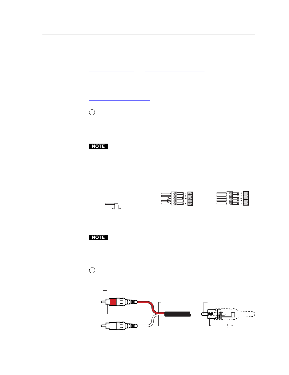
RCA connector audio inputs (RCA audio connector [A RCA] models only) —
Each input has a pair (left and right) of RCA connectors for unbalanced stereo
audio input (figure 2-5).
Sleeve (Gnd )
Tip (+)
Sleeve ( )
Right Channel
(Red Jacket)
Left Channel
(White Jacket)
Tip (Signal)
Figure 2-5 — RCA connector wiring