Digital i/o (digital, Input/output) ports, Ebus – Extron Electronics IPCP Pro Series User Guide User Manual
Page 26: Ports, Preliminary, 0 vdc — port on, logic low, Ebus port —this port is reserved for future use
IPCP Pro Series • Hardware Features and Installation
20
I
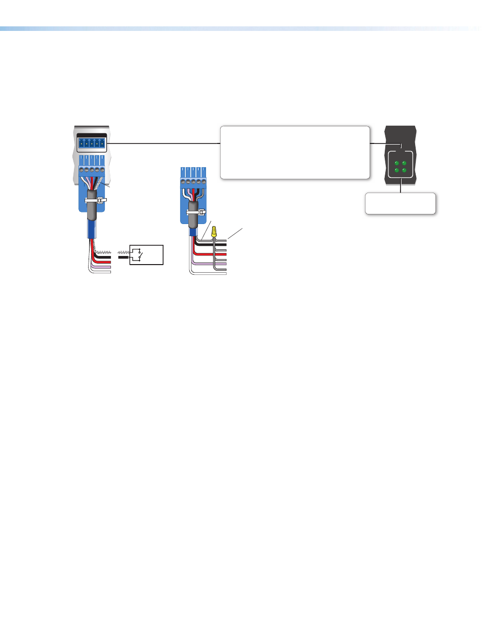
Digital I/O (digital input/output) ports — These ports work the same way the flex
I/O ports work, but they do not offer analog input, and thresholds are not adjustable.
Connect switches, sensors, LEDs, relays, or similar items to these ports, which can be
configured as digital inputs or outputs, with or without +5 VDC pull-up. These ports can
trigger events or functions (such as triggering relays, issuing commands, or sending an
e-mail) that have been configured using Global Configurator.
1 2 3 4 G
DIGITAL I/O
I/O
3
1
4
2
Share the same ground among
digital I/O connections.
Ground
Wire
Nut
Device 4
Device 3
Device 2
Device 1
Digital I/O (digital input/output)
Configure each port as as a digital input or output,
with or without +5 VDC pull-up.
Use these ports to:
• Monitor or trigger events and functions (toggle relays, issue
commands, send e-mail), once configured.
• Power LEDs, incandescent lights, or other devices that accept
a TTL signal.
Digital I/O LEDs
Light when the corresponding
ports are active.
Rear Panel
Front Panel
(Switches, sensors,
LEDs, relays, or
similar items)
Switch,
Sensor
2
1
3
4
G
Heat
Shrink
Over
Shield
Wires
Figure 15.
Digital I/O Port Wiring Examples
Digital input — To allow the IPCP to monitor external devices that do not use RS-232
communication, connect a switch, motion sensor, moisture sensor, tally feedback
output, button pad, or a similar item to a digital I/O port and configure it for digital input.
When configured as a digital input, the port is set to measure two states: high and low.
The port accepts 0 to 25.3 VDC input.
For digital I/O ports, threshold voltages are
not adjustable, unlike flex I/O ports.
Thresholds are:
•
2.0 VDC — port on, logic low
•
2.8 VDC — port off, logic high
There is also an internal, +5 VDC, selectable, pull-up resistor for this circuit.
Digital output — To power LEDs, incandescent lights, or other devices that accept a
TTL signal, or to provide contact closure control for projector lifts, motorized screens,
room or light switches via an Extron IPA T RLY4 or similar device, you can use one or
more of these ports as a digital output. When a port is configured for digital output, it
offers two output states: on and off.
•
When the port is set to an “on” state, (the circuit is closed), the I/O pin is connected
to ground. Output voltage is less than 0.5 volts.
•
When the port is set to the “off” state (the circuit is open), the output pin is not
connected. If the application calls for TTL compatibility, the digital output circuit can
be set up to provide a 2k ohm pull-up resistor to +5 VDC.
•
If the pull-up resistor is
disabled, voltage output is determined by an external
source device.
•
If the pull-up resistor is
enabled, voltage output is 4.3 VDC.
Each I/O port is capable of accepting 250 mA, maximum.
J
eBUS port —This port is reserved for future use.
J
eBUS is a technology (proprietary bus architecture and serial communication protocol)
developed by Extron. It allows many control accessories (known as “endpoints”) to be
connected to a single control processor to expand the capabilities of a control system.
It also supports greater distances, system configuration flexibility (both daisy chain
and hub-and-spoke topologies), and more functions than previously available bus
structures. Endpoints are automatically recognized by the host control processor and
can be added or removed at any time.
See the eBUS Technology Reference Guide before you install eBUS endpoint
products (such as button panels). It explains how to determine how many endpoints
are supported when directly connected to the control processor and where (at what
distances and what points in a system) and when it is advisable to add external eBUS
power inserters. Also see the guides for each endpoint device for detailed installation
information specific to each product, such as how to set the eBUS address and mount
the devices. Each endpoint device in a system must have a distinct eBUS address that
is not shared with any other device in the same system.
Wire both ends the same on each cable that connects eBUS devices. Extron Comm-
Link cable is recommended for these connections (see the tips and
eBUS
eBUS
+V +S -S G
PWR OUT = 9W
+V +S -S G
PWR OUT = 9W
EBD CR 44
R
INPUT
RELAY
eBUS/
STATUS
1
2
1
2
3
4
3
4
VIDEO
PC
MUTE
LAPTOP
VOLUME
DISPLAY
OFF
ON
MUTE
VOLUME
MENU
DISPLAY
SUB-
TITLE
OK
S LIMIT
eBUS
OVER
eBUS Accessory Port
Connect the first eBUS endpoint device to this port,
then connect other eBUS endpoints to that device in the
desired topology (daisy chain and/or hub-and-spoke).
• Wire the connectors the same at both ends for every
eBUS device.
• See the eBUS Technology Reference Guide for the
recommended distance from the control processor to the
last eBUS device.
• The IPCP provides power to the endpoint devices.
eBUS port on
an eBUS
endpoint
device
(button panel
or similar
device)
+S
+V
-S
G
+ Signal
+12 VDC
- Signal
Ground
eBUS Status LED (green)
LED is not lit — This indicates one of the following
conditions:
• No power is present.
• No eBUS devices are detected.
LED is blinking — An eBUS ID conflict (such as one
of the following items) has occurred:
• Two endpoints have the same bus ID number.
• An endpoint has a reserved bus ID number (zero).
LED is lit solid — Power is present with confirmed
communication and there are no eBUS ID conflicts
in the entire system.
Rear Panels
Front Panel
or
eBUS Limit LED (amber)
Lights solid and remains lit while
the eBUS port uses the
maximum threshold power.
eBUS Overload LED (red)
Lights solid red when the eBUS
port exceeds maximum
threshold power usage and
enters the fault state.
During this fault state, eBUS
port power is shut down until the
power usage falls back below
the threshold. The Over LED
remains lit during the fault state.
Figure 16.
eBUS Port Cabling and Front Panel LED Indication
This port provides power to endpoint devices. If the power draw by the connected
devices reaches the maximum level allowed, the eBUS Limit LED lights. If the power
consumption exceeds the allowed threshold, the IPCP shuts off the eBUS port and
lights the eBUS Over LED. If that occurs, you must resolve the hardware cause of the
power overload before the IPCP can successfully restore function to this port.
If the eBUS port is disabled, the user must disconnect or fix the attached eBUS devices
to correct the problem. After a specified period, the port attempts to restore power
and function. If the power draw is still excessive, the it turns off again for a specified
period. The IPCP will keep trying to restore power at specific intervals. If you correct the
overload, you can re-enable power output via software or wait for the unit to recheck
the port and restore power on its own.
PRELIMINARY