Front panel features, Ir learning receiver, Front panel – Extron Electronics IPCP Pro Series User Guide User Manual
Page 16: Features, Preliminary, Figure 5. ipcp pro series front panels, Ipcp pro 350, Ipcp pro 550
IPCP Pro Series • Hardware Features and Installation
10
Front Panel Features
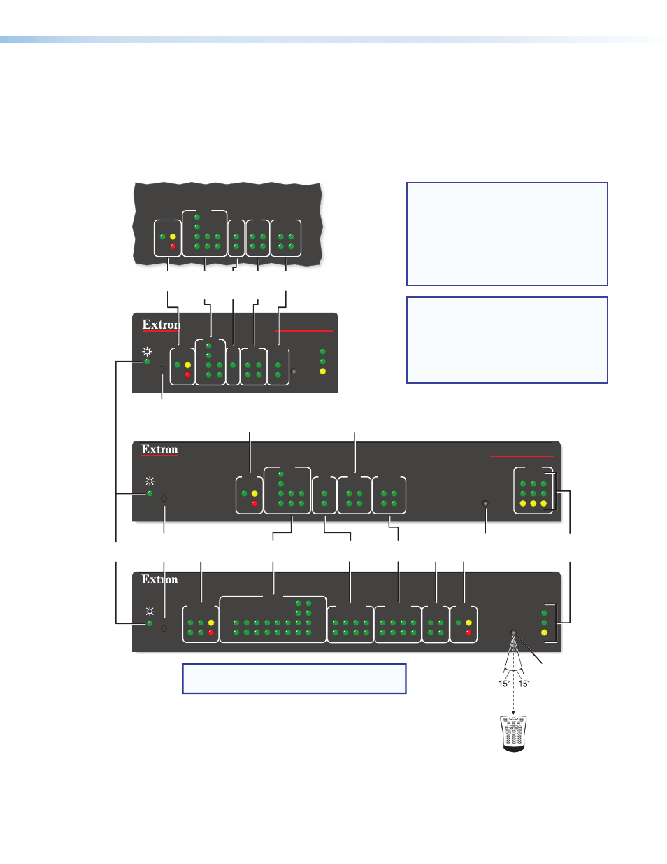
Front panel features are shown below. The quantity and location of ports and corresponding
front panel LEDs differ among IPCP models. However, the functions of each type of port
and their LEDs are identical for all models. Most of the features and LED indications are
described and shown in the “Rear Panel Features and Connections” section paired with the
descriptions of the corresponding rear panel ports.
R
IPCP PRO 350
1000
LINK
ACT
IR
LAN
1
2
3
2
1
LIMIT
R
IR
Tx
Rx
Tx
Rx
RTS
CTS
COM
IR/SERIAL
RELAYS
FLEX
I/O
S LIMIT
eBUS
SWITCHED
12 VDC
1000
LINK
ACT
IPCP PRO 550
OVER
4
3
1
2
3
4
5
6
7
8
OVER
5
6
7
8
2
1
3
4
2
1
3
4
5
6
7
8
2
1
3
4
COM
I/O
RELAYS
IR/S
3
1
4
2
3
1
4
2
1
2
2
3
1
S LIMIT
eBUS
OVER
Rx
CTS
RTS
Tx
S LIMIT
eBUS
OVER
RTS
1
CTS
Tx
2
Rx
COM
3
1
4
2
I/O
RELAYS
1
2
IR/S
R
1000
LINK
ACT
IR
IPCP PRO 250
S LIMIT
eBUS
OVER
Rx
CTS
RTS
Tx
COM
I/O
RELAYS
IR/S
3
1
4
2
3
1
4
2
1
2
2
3
1
NOTE: Numbers adjacent to LEDs correspond
to the like-numbered rear panel ports.
Switched
12 VDC
LEDs
COM (Serial)
LEDs
COM
(Serial)
LEDs
IR/Serial
LEDs
IR/
Serial
LEDs
Flex I/O
LEDs
Flex
I/O
LEDs
Reset
Button
(recessed)
Reset Button
(recessed)
eBUS LEDs
eBUS
LEDs
Power
LED
IR Receiver
Relay
LEDs
Relay
LEDs
eBUS LEDs
1
2
3
4
5
6
7
8
0
9
2–12"
(4–30 cm)
IR Receiver
IR Learning Angle
and Distance
LAN/
Network
LEDs
Digital I/O LEDs
IPCP Pro 350M
(within another device)
Figure 5.
IPCP Pro Series Front Panels
NOTE: The control processor must be
set up in order to function.
See the
section
starting on page 25 and the Global
Configurator Help file for information
about Global Configurator, which you
must use to set up the unit.
NOTES:
•
The Reset button and power LED
for the IPCP Pro 350M are located
next to the rear panel connectors.
•
For reset mode information, see
IR Learning Receiver
In most cases, Extron has already produced a driver file for controlling the projector, display,
or source device you plan to use. If a device driver file is not available, you can create your
own using Extron IR Learner software, the remote control of the projector or display, and the
IR learning receiver sensor on the IPCP, shown the figure above.
PRELIMINARY