Quick start — dds 100, Installation, Step 1 – Extron Electronics DDS 100 User Manual
Page 3: Step 2, Step 3, Step 4, Step 5, Step 6, Step 7
Quick Start — DDS 100
Installation
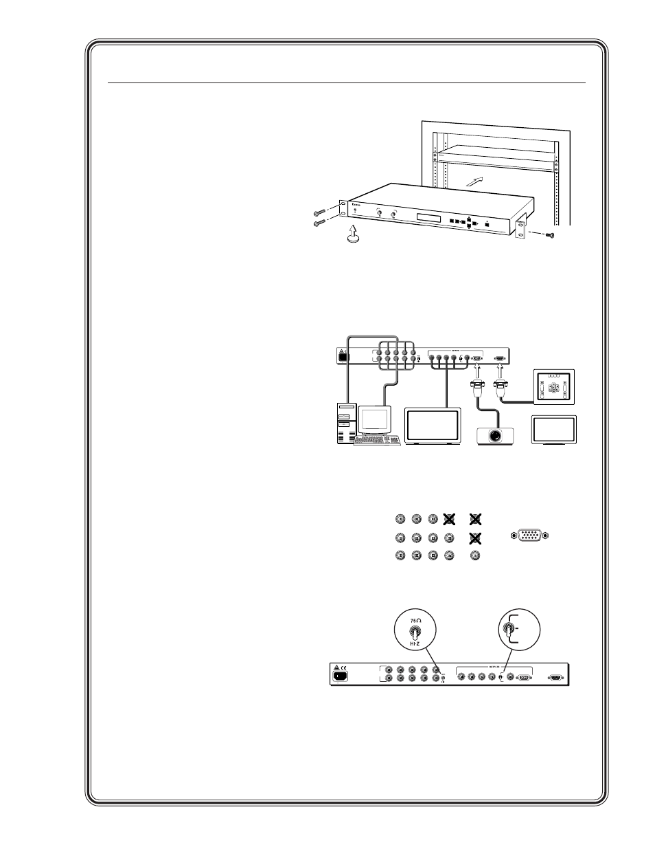
Step 1
Install the four rubber feet on the bottom
of the DDS 100 digital display scaler
(1A), or mount the scaler in a rack (1B).
Step 2
Turn off power to the input and output
devices, and remove the power cords
from them.
Step 3
Attach the scaler to the input device, and
attach the output device to the scaler
(3A). It does not matter which set of
input connectors you use.
Input options (3B) are:
RGsB (connected to R, G, and B)
RGBS (connected to R, G, B, and H/HV)
RGBHV (connected to R, G, B, H/HV,
and V).
Output options are the same as the input
options plus VGA/XGA/SVGA/SXGA.
Connect only one input device and one
output device.
Step 4
Either attach a local monitor to the
unused set of input connectors and set
the 75
Ω
/Hi Z switch (4) to Hi Z, or
attach BNC 75
Ω
termination adapters to
the H/HV and V connectors of the
unused set of input connectors and set
the 75
Ω
/Hi Z switch to 75
Ω
.
Step 5
Set the sync selection switch (5) to the
desired output sync format. The format
must correspond to the output cables
connected. (H = RGBHV, HV = RGBS,
SOG = RGsB.)
Step 6
Plug the scaler, input device, and output
device into a grounded AC source, and
turn on the input and output devices.
Step 7
Use the LCD menu screens to configure
the scaler (see the next page).
RGsB
R
H/HV
G
B
V
R
H/HV
G
B
V
R
H/HV
G
B
V
RGBS
RGBHV
VGA OUT
50/60 Hz 0.5A
100-240
INPUT/
LOOP OUT
R
G
B
H/HV
V
H
HV
SOG
R
G
B
H/HV
V
VGA OUT
Input
Output
or
or
RS-232
REMOTE
50/60 Hz 0.5A
100-240
INPUT/
LOOP OUT
R
G
B
H/HV
V
H
HV
SOG
R
G
B
H/HV
V
VGA OUT
RS-232
REMOTE
MENU
FREEZE/
RESET
NEXT
DDS 100
DIGITAL DISPLA
Y SCALER
CENTERING/PAN
Mounting Bracket
Each Side with
# 8 Screw (4 Plcs)
High Resolution
Workstation
Plasma
Display
LCD
Projector
LCD
Display
RS-232 Control
1A
3A
3B
4
5
1B
Rubber Feet
Bottom Side
(4 Plcs)
or
H
HV
SOG