Rear panel features – Extron Electronics DDS 100 User Manual
Page 13
2-3
DDS 100 Installation
Rear panel features
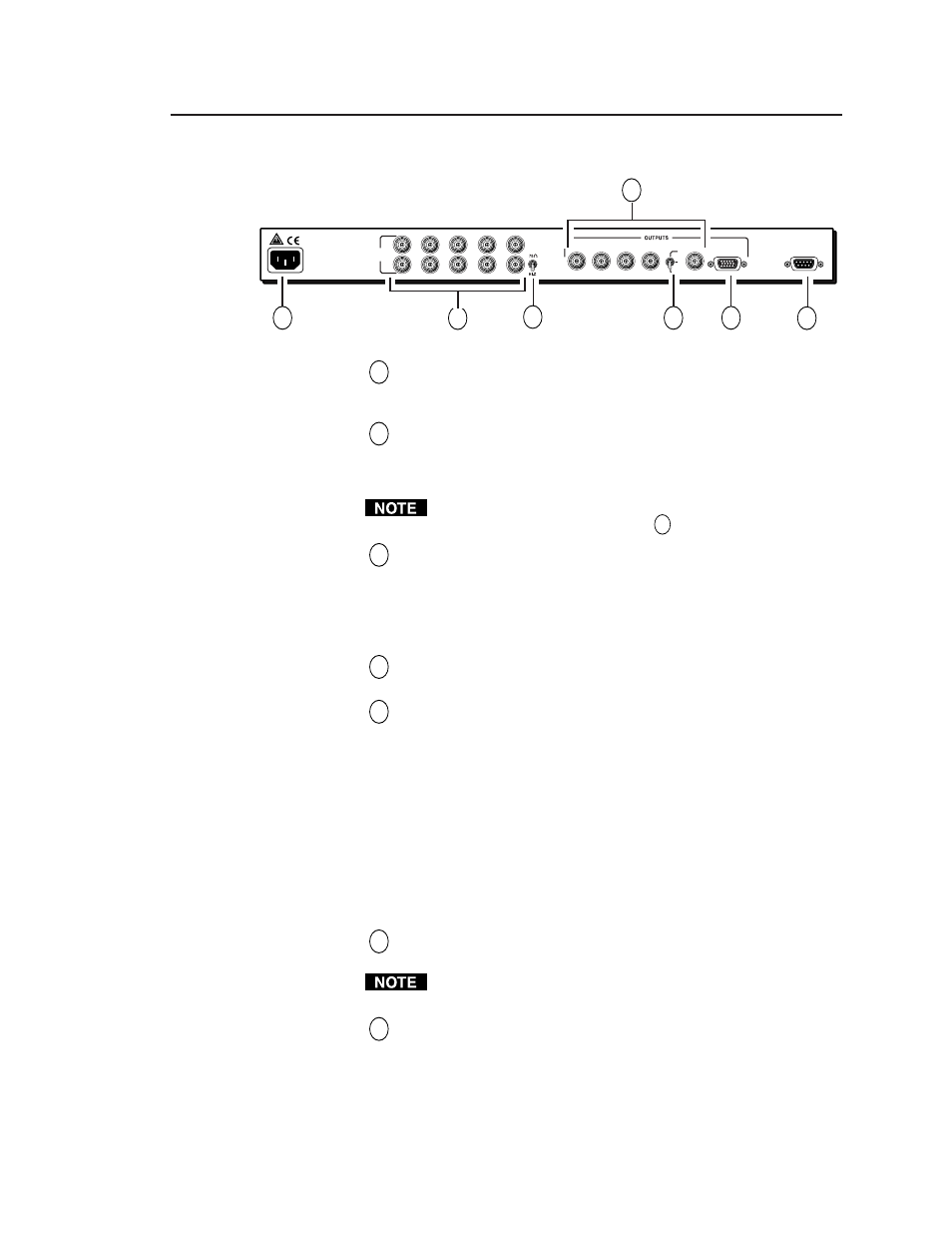
Figure 3 — DDS 100 rear panel
1
AC power connector —
Standard AC power connector attaches
the scaler to any power source from 100VAC to 240VAC, operating
at 50 Hz or 60 Hz.
2
Input connectors —
BNC female connectors for RGsB (sync on
green), RGBS (composite sync), or RGBHV input. One set of
connectors is used for the input device, and one set is available for
a local monitor, if desired.
You must set the 75
Ω
/Hi-Z switch to correspond to the presence or
absence of a local monitor. See item
3
below.
3
75
Ω
Ω
Ω
Ω
Ω
/Hi-Z switch —
Provides termination for computer video
input. Set the switch to 75
Ω
Ω
Ω
Ω
Ω
if no local monitor is attached to the
scaler, and install two BNC 75-ohm termination adapters, one on
the H/HV input BNC connector, and one on the V input BNC
connector, of the unused set of input BNC connectors. Set the
switch to Hi-Z if a local monitor is attached.
4
Output connectors —
BNC female connectors for RGsB (sync on
green), RGBS (composite sync), or RGBHV output.
5
Sync selection switch —
Allows you to choose how the sync
output signals will be routed:
H —
If the switch is set to H, the scaler outputs separate
horizontal and vertical sync signals; only horizontal sync is
routed through the H/HV output connector.
HV —
If the switch is set to H/V, the scaler outputs a composite
sync signal (H and V combined) on the H/HV output
connector.
SOG —
If the switch is set to SOG (sync on green), the scaler
outputs a composite sync signal on the green video signal
via the G output connector.
6
VGA output connector —
15-pin HD female VGA connector for
the output projector.
You can connect only one output device. Do not connect two
output devices, or the scaler will be double-terminated.
7
RS-232 connector —
9-pin D female connector that allows you to
attach a computer or controlling device for remote control of the
DDS 100.
4
50/60 Hz 0.5A
100-240
INPUT/
LOOP OUT
R
G
B
H/HV
V
H
HV
SOG
R
G
B
H/HV
V
VGA OUT
RS-232
REMOTE
2
3
5
6
7
1