Installation, cont’d, Cabling – Extron Electronics DDS 100 User Manual
Page 16
Installation, cont’d
DDS 100 Installation
2-6
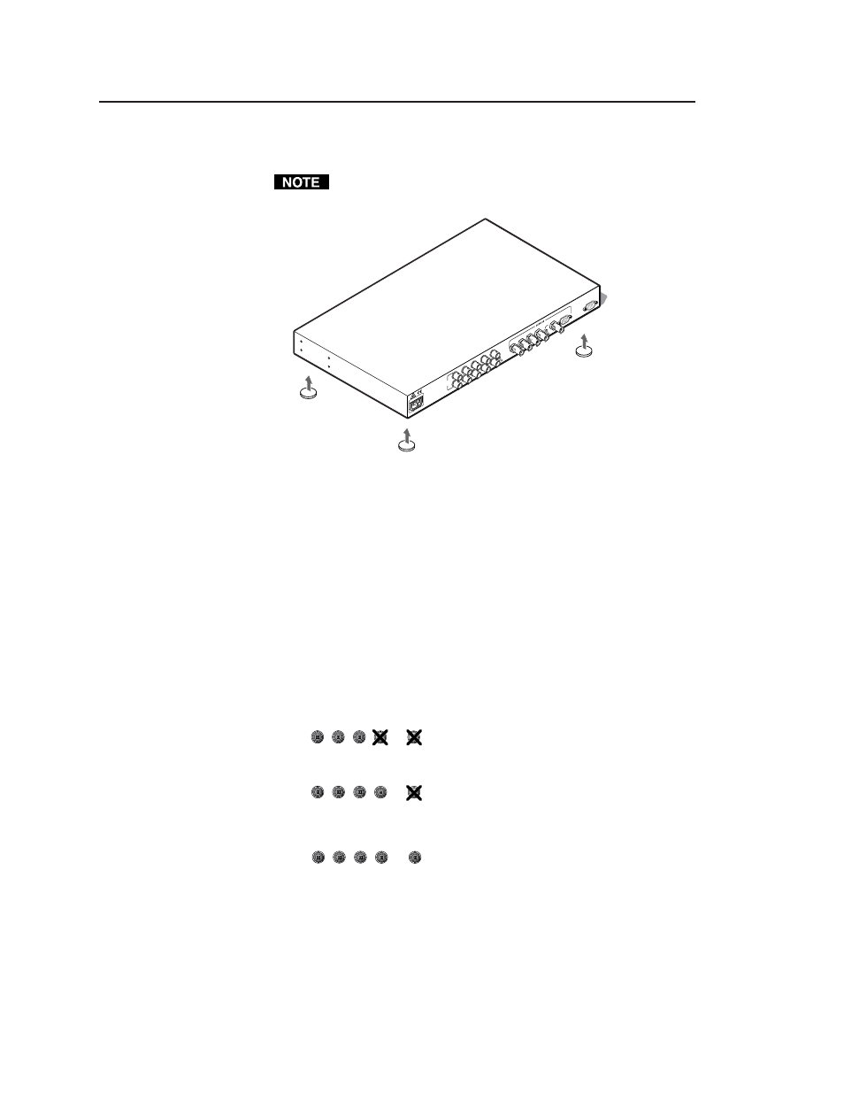
3. Place the rubber foot on one corner of the scaler as shown in figure 6,
and press it into place.
Position each rubber foot carefully before pressing it into place. It is
difficult to move a foot after it is in place.
Figure 6 — Installing the rubber feet
4. Repeat steps 2 and 3 to install a rubber foot on each of the remaining
corners of the scaler.
5. Turn the DDS 100 right side up and place it in the desired installation
location.
Cabling
The scaler can connect to an input device, such as an interface that is
attached to a high-resolution workstation, and to an output device, such
as an LCD projector, LCD display, or plasma display. Refer to figure 7 as
you connect the devices.
Use the following information when attaching both input and output
cables to the scaler.
RGsB
— If coax cables are connected and terminated (75 ohms) to
the red, green, and blue channels only,
the format will be sync on green.
RGBS
— If coax cables are connected and terminated (75 ohms) to
the R, G, B, and H/HV (composite sync)
channels, the format will be composite
sync.
RGBHV
— If coax cables are connected and terminated (75 ohms)
to the R, G, B, H/HV, and V channels, the
format is separate horizontal and vertical
sync.
R
H/HV
G
B
V
R
H/HV
G
B
V
Rubber Feet
(4 Plcs) Bottom Side
50
/60
H
z
0.5
A
10
0-2
40
INPUT/
LOOP OUT
R
G
B
H/HV
V
H
HV
SO
G
R
G
B
H/HV
V
VGA OUT
RS-232
REMO
TE
R
H/HV
G
B
V