Extron Electronics DDS 100 User Manual
Page 17
2-7
DDS 100 Installation
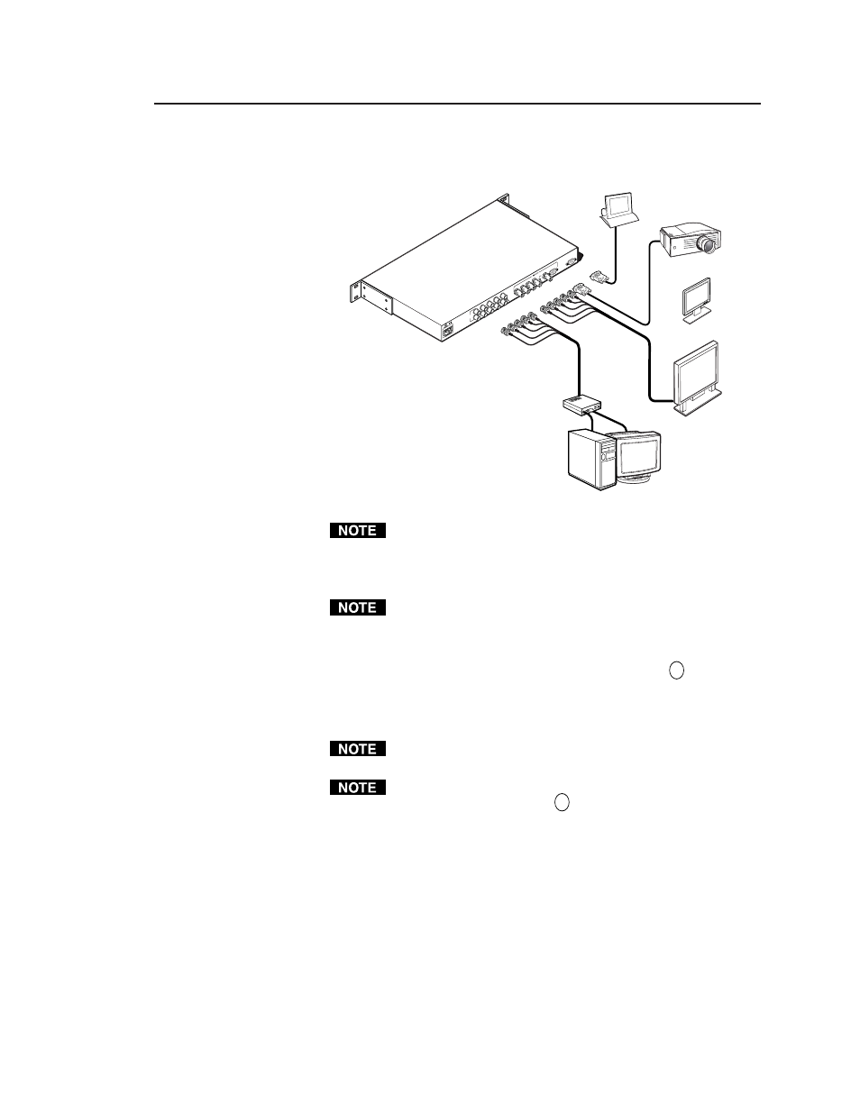
RS-232 Control
Plasma Display
LCD Display
DDS 100
or
or
50
/60
H
z
0.5
A
10
0-2
40
IN
PU
T/
LO
OP
O
UT
R
G
B
H/
HV
V
H
HV
SO
G
R
G
B
H/
HV
V
VG
A
OU
T
RS
-23
2
RE
MO
TE
High Resolution
Workstation
LCD Projector
Interface
INPUT
OUTPUT
1. Use BNC connectors to connect the input device to the input/loop
out connectors. It does not matter whether you use the top or
bottom row of connectors.
Figure 7 — Connecting the scaler
If there is no video input, no video output appears through the
output device.
2. If desired, attach a local monitor to the remaining row of input BNC
connectors.
If a local monitor is attached, set the 75
Ω
/Hi-Z switch to Hi-Z. If a
local monitor is not attached, set the 75
Ω
/Hi-Z switch to 75
Ω
Ω
Ω
Ω
Ω
, and
install two BNC 75-ohm termination adapters, one on the H/HV
input BNC connector, and one on the V input BNC connector, of
the unused set of input BNC connectors. See item
3
on page 2-3
for more information.
3. Use BNC connectors or a 15-pin HD VGA/XGA/SVGA/SXGA
connector to connect the scaler to the output device.
You can connect only one output device. Do not connect two
output devices, or the scaler will be double-terminated.
You must set the three-position sync selection switch to match the
cabled sync format. See item
5
on page 2-3 for more information.