Installation, cont’d, Setting configuration switches, Installation overview – Extron Electronics DDS 100 User Manual
Page 14
Installation, cont’d
DDS 100 Installation
2-4
Setting Configuration Switches
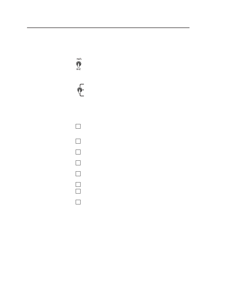
The DDS 100 includes two toggle switches on the back panel.
The two-position switch allows you to select 75
Ω
or Hi-Z termination.
Set the switch to the top position, labeled 75
Ω
Ω
Ω
Ω
Ω,
if no local
monitor is attached to the scaler. Set the switch to the bottom
position, labeled Hi-Z, if a local monitor is attached.
The three-position switch allows you to select between RGBHV
(separate horizontal and vertical sync), RGBS (composite
sync), and RGsB (sync on green). Set the toggle switch to
the top position, labeled H, for RGBHV output. Set the
switch to the middle position, labeled HV, for RGBS
output. Set it to the bottom position, labeled SOG, for
RGsB output.
Installation Overview
To install the DDS 100 for basic operation, follow these general steps:
1
If desired, mount the scaler in a rack (see “Mounting the scaler”
below). Otherwise, install the rubber feet (see “Installing the
rubber feet” on page 2-5).
2
Turn off power to the input and output devices, and unplug the
power cables from them.
3
Attach the scaler to the input device, and attach the output device
to the scaler. See “Cabling” on page 2-6.
4
Set up the configuration switches. See “Setting configuration
switches” above for details.
5
Plug the scaler, input device, and output device into a grounded
AC source.
6
Turn on the input and output devices.
7
Use the LCD menu screens to configure the scaler. See
“Operation”, chapter 3.
8
The image from the input device should appear on the output
device. If it does not, double check steps 3 and 4 and make
adjustments as needed.
Mounting the scaler
The DDS 100 ships with four uninstalled rubber feet. If you are going to
rack mount the unit, do so before cabling the unit, and do not install the
rubber feet. If you are not rack mounting the scaler, skip to “Installing
the rubber feet” on page 2-5.
H
HV
SOG