6 process variable monitoring, 7 alarms/events – Xylem 10 001 262R5 AquaForce Pump Controller User Manual
Page 44
AQUAFORCE Installation, Operation, and Maintenance
38
Operation
5.6 Process Variable Monitoring
To view the actual process variable signals that are being sent to the controller press the
PV/1 key.
The following will be displayed:
ACT = ###
SP1 = ###
HZ = ##
The # symbol will be replaced by the actual value of process variables and set points.
5.7 Alarms/Events
When the controller detects an alarm/event condition, the display will flash *ALARM/EVENT* in the lower
right corner of the main screen.
The green LED on the
HELP key will also flash during an alarm/event condition. Press the HELP key for
additional information on the alarm(s)/event(s). If there are more than one alarm(s)/event(s), the alarm(s)/
event(s) will be listed in order of occurrence.
To view possible causes for alarm/event, press the
HELP key again after the alarm/event is displayed. Refer to
table below for an overview of the possible alarm/event and their respective causes.
Press the
CLEAR key to return to the main screen. After addressing the source of the alarm/event, press
RESET to re-start the system and/or clear the alarm/event.
The controller logs alarm/event as they occur to aid in troubleshooting unobserved alarm/event. Refer to
Section 6.14.0 for alarm/event logging information
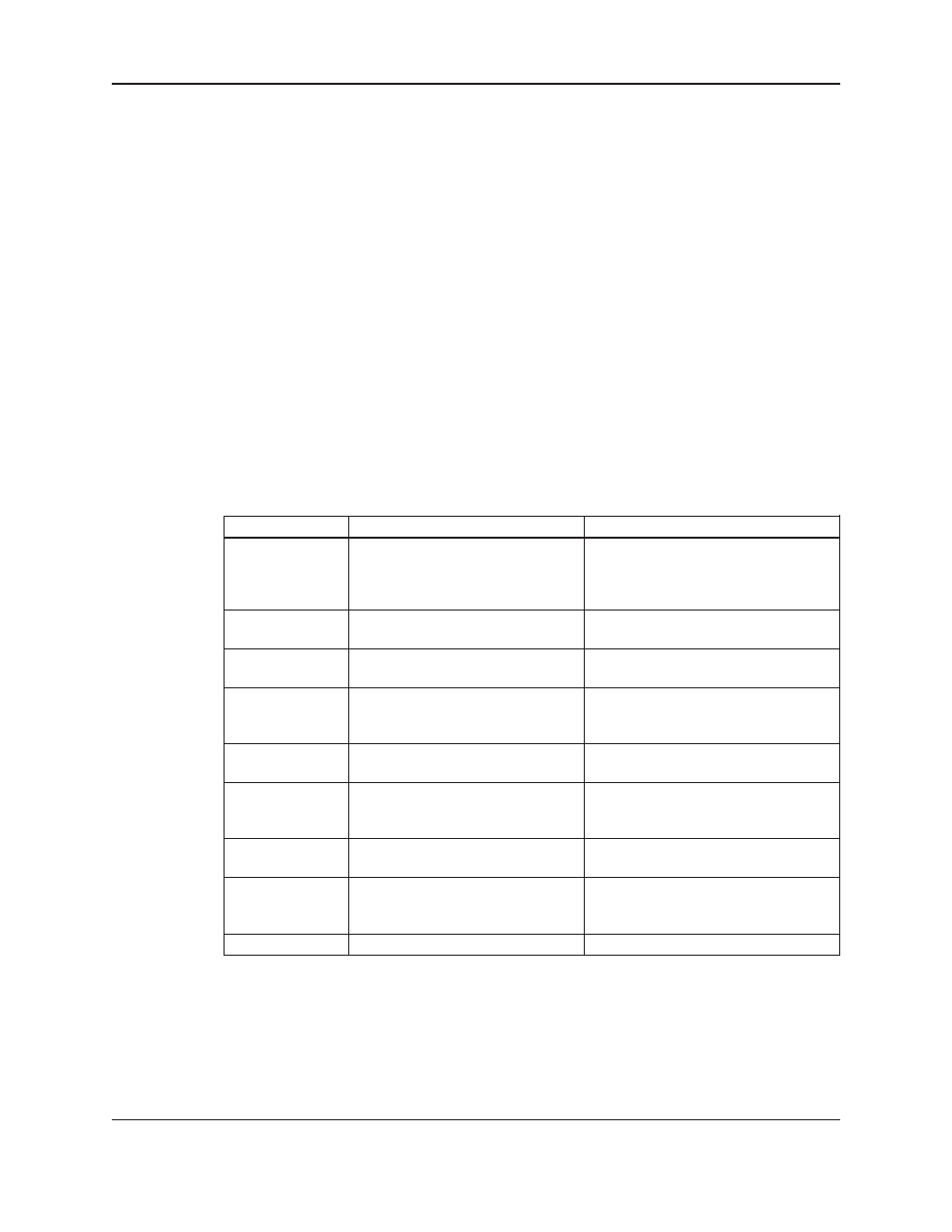
Help Screen Alarm Help/Help Screen Display
Detailed Description
VFD
Failure
“Check
communication
wiring,
and
VFD
display”
High Discharge
“Check discharge pressure –
manual RESET required”
Low Discharge
“Check discharge pressure”
Low Suction
“Check setting of the low suction
switch” or low suction settings in the
ALARM/EVENTS set up
Low Water
“Check setting of level switch”
NFSD
“System will restart automatically
when flow occurs”
Sensor Fail
“Check wiring, piping, polarity,
continuity”
Sensor Reading
“Check wiring of both sensors, and
Drift
compare the pressure reading of both
sensors with pressure gauge ”
Low Battery
Replace OIP battery
Replace OIP battery
The controller is not receiving a closed run
signal from VFD number X after it has been
given a start command or communication
failure or VFD fault
Check the pressure setting in the setup
menu.
Check the pressure setting in the setup
menu.
Check for open or closed contacts and low
suction settings, refer to wire diagram for
proper connection
Check for open or closed contacts, refer to
wire diagram for proper connection.
Check the Reset PSI Drop value and the
pressure sensor connections, refer to the
wire diagram.
The controller is not receiving the proper
4-20mA
“Check wiring of both sensors, and compare
the pressure reading of both sensors with
pressure gauge ”