Xylem 10 001 262R5 AquaForce Pump Controller User Manual
Page 34
AQUAFORCE Installation, Operation, and Maintenance
28
Installation
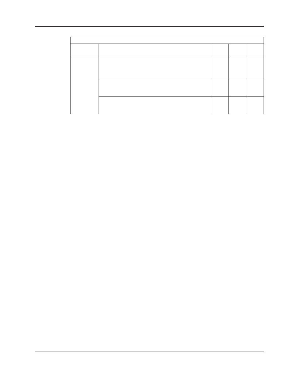
See following table for all
DISPLAY menu items.
Display Menu Items
Menu Item
Variable
Default Range Field
Value
Display
Delay to Display Status: ##
3
0-99
The time in minutes after which the fourth line at initial
system status screen will start showing system status if
any key has not been pressed
Status Line Refresh Rate: ##
10
0-99
The time in seconds prior to change the next system
status line
The time in minutes after which the backlight display
60
0-999
will turn off if a key has not been pressed. A value of 0
disables this function
4.10.22 Test set up
Paths: Status Screens / Set up(3) / Test(5)
The
TEST menu screen gets displayed:
Test Selection: #
1=DI 4=AO 7=Disp
2=DO 5=LED 8=Comm
3=AI 6=Key 9=VFD Comm
Press the numeric key corresponding to the desired sub-menu, and then press the
ENTER key.
4.10.23 Digital input test
Paths: Status Screens / Set up(3) / Test(5) / DI(1)
The Digital Input Test screen is displayed below:
Digital Inputs
1
2
3
# # #
Press Clear to Exit
The 0 below each corresponding input will change to a 1 upon receiving a 24VDC digital input on that channel.
Press
CLEAR key to exit the test.
4.10.24 Digital output test
Paths: Status Screens / Set up(3) / Test(5) / DO(2)
The Digital Output Test screen is displayed below:
Digital Outputs
1
2
# #
Enter DO# # (0=Exit)
Press the numeric key corresponding to the digital output for which the state is to be changed, and then press
ENTER to change it. Pressing ENTER multiple times will toggle between 0 and 1. A 1 indicates that the
corresponding relay is closed. When the relay is closed, the corresponding LED on the digital output module will
be lit. Press
0 and ENTER to exit the test.
Note: Any device connected to the relay will be energized.