Xylem 10 001 262R5 AquaForce Pump Controller User Manual
Page 31
AQUAFORCE Installation, Operation, and Maintenance
25
Installation
See following table for all
MODBUS menu items.
Modbus Menu Items
Menu Item
Variable
Default Range Field
Value
Modbus
Baud: #####
9600
9600,
The baud rate is user adjustable parameter
19200,
38400
Node: ###
10
0-255
The node number should be supplied by the BMS
communications port.
AI Ovrd: $
N
Y/N
Select “Y” to override analog inputs through the
communications port.
4.10.15 Analog Input Override
If “Y” was entered for “AI Ovrd” in any of the communication setup screens above, the following screen will be
automatically displayed:
AI Override
AI1: $ AI2: $
OK $(Y/N)
Enter a “Y” next to each analog input type that will be overridden through the communications port.
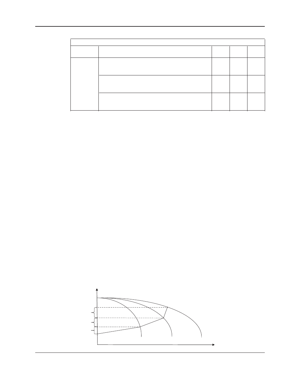
4.10.16 Dynamic Flow Loss Compensation:
This energy savings feature allows user to compensate for the friction losses of system. As flow increases, the
pressure losses due to friction in the system will increase accordingly. This feature will allow controller to modify
the setpoint in real time based on the speed changes to compensate system friction loss. The controller will log
the last 40 real time setpoint changes. Figure 1 shows how this function works with setup parameters using an
example of a three pump system.
Paths: Status Screens / Set up(3) / System(4) / Frict. Loss Comp. (11)
The Friction Loss Compensation screen has been displayed below:
Frict. Loss: ###
>
Auto: $
Enable: $
Log Stab Tmr: ###S
Log Reset: $
OK? $
Press the
YES/7 key to confirm the selection or Press next (►) key to go to the next screen. The display now
shows:
OK? $
Loss1 : ###
Loss4 : ###
Loss2 : ###
Loss3 : ###
Press the Y
ES/7 key to confirm the selection.
Figure 1
Loss1
Loss2
Loss3
H
Q
Setpoint - (Loss1 + Loss2 + Loss3)
Setpoint - (Loss2 + Loss3)
Setpoint - (Loss3)
Setpoint