Overtemperature protection, Thermal considerations, Figure 40. thermal test setup – GE Industrial Solutions NH050x-L Series User Manual
Page 14: Figure 41. temperature measurement location, Convection requirements for cooling, Feature descriptions
NH033x-L and NH050x-L Series Power Modules:
Data Sheet
5 Vdc Input; 1.2 Vdc to 3.3 Vdc Output; 10 A and 15 A
March 2010
14
14
Lineage Power
Feature Descriptions
(continued)
Overtemperature Protection
To provide additional protection in a fault condition, the
unit is equipped with a nonlatched thermal shutdown
circuit. The shutdown circuit engages when Q32
exceeds approximately 120 °C. The unit attempts to
restart when Q32 cools down. The unit cycles on and
off if the fault condition continues to exist. Recovery
from shutdown is accomplished when the cause of the
overheating condition is removed.
Thermal Considerations
The power modules operate in a variety of thermal
environments; however, sufficient cooling should be
provided to help ensure reliable operation of the unit.
Heat is removed by conduction, convection, and radia-
tion to the surrounding environment.
The thermal data presented is based on measure-
ments taken in a wind tunnel. The test setup shown in
Figure 40 was used to collect data for Figures 50 and
51. Note that the airflow is parallel to the long axis of
the module. The derating data applies to airflow along
either direction of the module’s long axis.
The module runs cooler when it is rotated 90° from the
direction shown in Figure 40. This thermally preferred
orientation increases the maximum ambient tempera-
tures 4 °C to 5 °C from the maximum values shown in
Figures 50 and 51.
8-1199(C).a
Note: Dimensions are in millimeters and (inches).
Figure 40. Thermal Test Setup
Proper cooling can be verified by measuring the power
module’s temperature at lead 7 of Q32 as shown in
Figure 41.
8-1149(C).b
Figure 41. Temperature Measurement Location
The temperature at this location should not exceed
115 °C at full power. The output power of the module
should not exceed the rated power.
Convection Requirements for Cooling
To predict the approximate cooling needed for the mod-
ule, determine the power dissipated as heat by the unit
for the particular application. Figures 42 through 49
show typical power dissipation for the module over a
range of output currents.
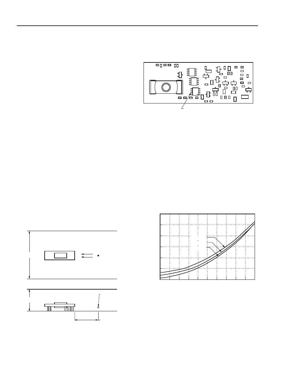
8-2446(C)
Figure 42. NH033M-L Typical Power Dissipation vs.
Output Current, T
A
= 25 °C
AIRFLOW
203.2 (8.0)
76.2 (3.0)
AIR VELOCITY
AND AMBIENT
TEMPERATURE
MEASURED HERE
POWER MODULE
25.4 (1.0)
LEAD #7
Q32
1
2
6
7
8
9
0.5
3.0
OUTPUT CURRENT, I
O
(A)
2.0
1.5
2.5
10
0
3.5
1.0
4
5
3
V
I
= 5.5 V
V
I
= 5.0 V
V
I
= 4.5 V
PO
WER DISSIP
A
TION,
P
D
(W)