Test configurations, Figure 33. input reflected-ripple test setup, Design considerations – GE Industrial Solutions NH050x-L Series User Manual
Page 11: Input source impedance, Lineage power 11, Is less than 1 µh (see figure 36), X 100
Data Sheet
NH033x-L and NH050x-L Series Power Modules:
March 2010
5 Vdc Input; 1.2 Vdc to 3.3 Vdc Output; 10 A and 15 A
Lineage Power
11
Test Configurations
8-203(C).h
Note: Input reflected-ripple current is measured with a simulated
source impedance of 500 nH. Capacitor C
S
offsets possible
battery impedance. Current is measured at the input of the
module.
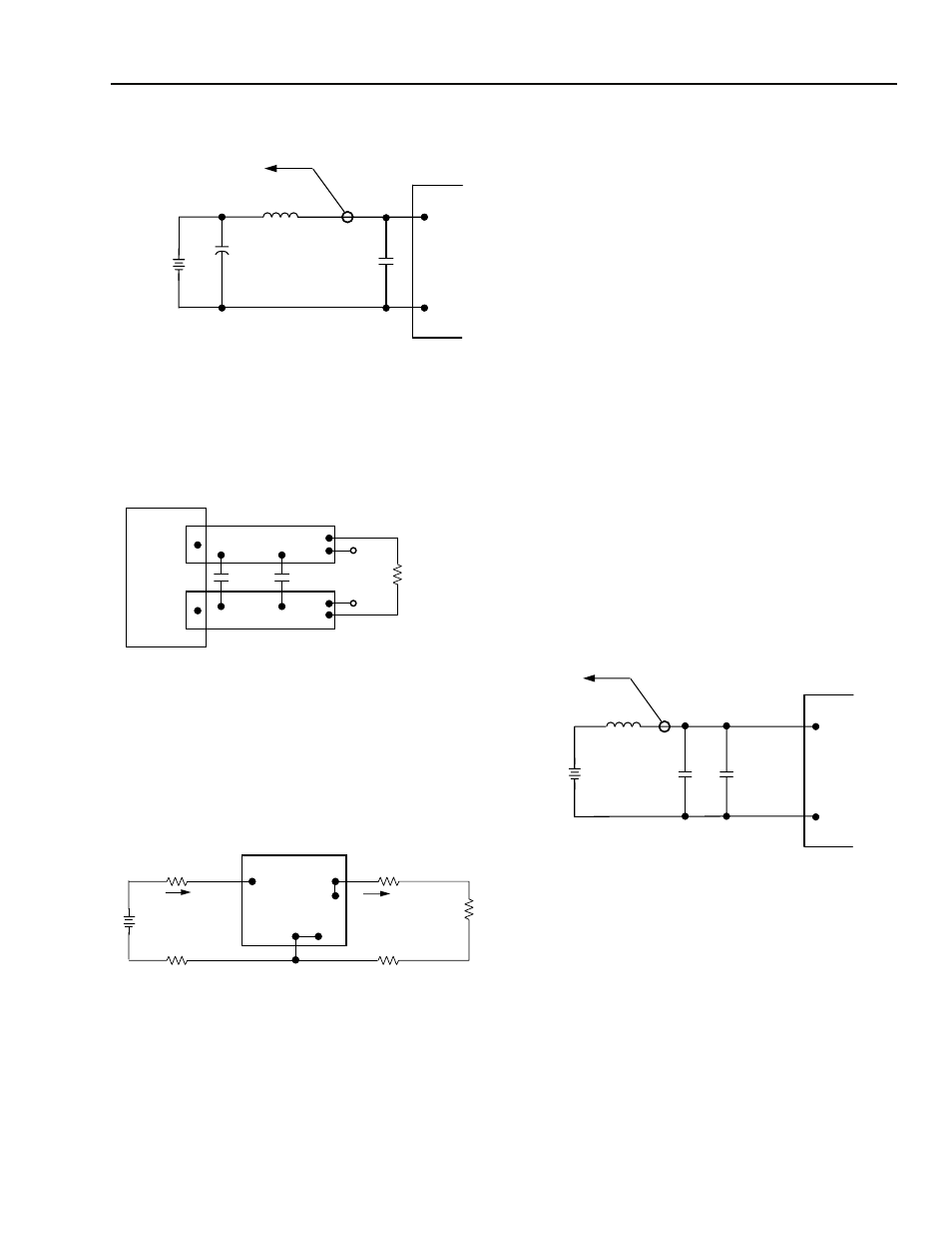
Figure 33. Input Reflected-Ripple Test Setup
8-513(C).r
Note: Use a 0.1 µF ceramic capacitor and a 1,000 µF aluminum or
tantalum capacitor (ESR = 0.05 ¾ @ 100 kHz). Scope mea-
surement should be made using a BNC socket. Position the
load between 50 mm and 80 mm (2 in. and 3 in.) from the
module.
Figure 34. Peak-to-Peak Output Noise
Measurement Test Setup
8-1173(C).a
Note: All measurements are taken at the module terminals. When
socketing, place Kelvin connections at module terminals to
avoid measurement errors due to socket contact resistance.
Figure 35. Output Voltage and Efficiency
Measurement Test Setup
Design Considerations
Input Source Impedance
The power module should be connected to a low ac-
impedance input source. Highly inductive source
impedances can affect the stability of the NH033x-L
and NH050x-L Series Power Modules. Adding external
capacitance close to the input pins of the module can
reduce the ac impedance and ensure system stability.
The minimum recommended input capacitance (C
1
) is
a 470 µF electrolytic capacitor with an ESR ð 0.02
Ω @
100 kHz. Verify the quality and layout of these capaci-
tors by ensuring that the ripple across the module input
pins is less than 1 Vp-p at I
O
= I
O, max
. (See Figures 33,
The 470 µF electrolytic capacitor (C
1
) should be added
across the input of the NH033x-L or NH050x-L to
ensure stability of the unit. The electrolytic capacitor
should be selected for ESR and RMS current ratings to
ensure safe operation in the case of a fault condition.
The input capacitor for the NH033x-L and NH050x-L
series should be rated to handle 10 Arms.
When using a tantalum input capacitor, take care not to
exceed the tantalum capacitor power rating because of
the capacitor’s failure mechanism (for example, a short
circuit).
8-1215(C).a
Figure 36. Setup with External Capacitor to Reduce
Input Ripple Voltage
To reduce the amount of ripple current fed back to the
input supply (input reflected-ripple current), an external
input filter can be added. Up to 10 µF of ceramic
capacitance (C
2
) may be externally connected to the
input of the NH033x-L or NH050x-L, provided the
source inductance (L
SOURCE
) is less than 1 µH (see
Figure 36).
TO OSCILLOSCOPE
500 µH
C
S
220 µF
ESR < 0.1
Ω
@ 20 ˚C, 100 kHz
V
I
(+)
BATTERY
C
I
470 µF
CURRENT
PROBE
L
TEST
ESR < 0.2
Ω
@ 100 kHz
GND
V
O
1.0 µF
RESISTIVE
LOAD
SCOPE
COPPER STRIP
1000 µF
GND
V
I
V
O
I
I
I
O
SUPPLY
CONTACT RESISTANCE
CONTACT AND
DISTRIBUTION LOSSES
LOAD
GND
SENSE(+)
SENSE(-)
η
V
O
I
O
×
V
I
I
I
×
------------------------
x 100
=
%
TO OSCILLOSCOPE
1 µH (MAX)
C
2
V
I
GND
SUPPLY
CURRENT
PROBE
L
SOURCE
10 µF (MAX)
+
C
1
470 µF