Remote on/off (continued), Figure 38. remote on/off implementation, Remote sense – GE Industrial Solutions NH050x-L Series User Manual
Page 13: Output voltage set-point adjustment (trim), Overvoltage protection, Feature descriptions, Remote on/off
Data Sheet
NH033x-L and NH050x-L Series Power Modules:
March 2010
5 Vdc Input; 1.2 Vdc to 3.3 Vdc Output; 10 A and 15 A
Lineage Power
13
Feature Descriptions
(continued)
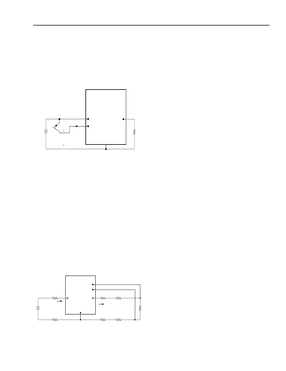
Remote On/Off
(continued)
CAUTION: Never ground the ON/OFF pin. Ground-
ing the ON/OFF pin disables an impor-
tant safety feature and may damage the
module or the customer system.
8-1175(C).a
Figure 38. Remote On/Off Implementation
Remote Sense
Remote sense minimizes the effects of distribution
losses by regulating the voltage at the remote-sense
connections. The voltage between the remote-sense
pins and the output pins must not exceed the output
voltage sense range given in the Feature Specifications
table.
The voltage between the V
O
and GND pins must not
exceed 110% of V
O, nom
for V
O
≥ 2.5 V or 120% of
V
O, nom
for V
O
< 2.5 V. This limit includes any increase
in voltage due to remote-sense compensation and out-
put voltage set-point adjustment (trim), see Figure 39.
If not using the remote-sense feature to regulate the out-
put at the point of load, connect SENSE(+) to V
O
and
SENSE(–) to GND at the module.
8-651(C).i
Figure 39. Effective Circuit Configuration for
Single-Module Remote-Sense Operation
Output Voltage Set-Point Adjustment
(Trim)
Output voltage set-point adjustment allows the output
voltage set point to be increased or decreased by con-
necting an external resistor between the TRIM pin and
either the SENSE(+) pin (decrease output voltage) or
SENSE(–) pin (increase output voltage). The trim
range for modules that produce 2.5 V
O
or greater is
±10% of V
O, nom
. The trim range for modules that pro-
duce less than 2.5 V
O
is +20%, –0%.
Connecting an external resistor (R
trim-down
) between the
TRIM and SENSE(+) pin decreases the output voltage
set point as defined in the following equation.
For the F (3.3 V
O
) module:
For the G (2.5 V
O
) module:
Note: Output voltages below 2.5 V cannot be trimmed
down.
Connecting an external resistor (R
trim-up
) between the
TRIM and SENSE(–) pins increases the output voltage
set point to V
O, adj
as defined in the following equation.
For the G (2.5 V
O
) module:
For all other modules:
Leave the TRIM pin open if not using that feature.
Overvoltage Protection
Overvoltage protection is not provided in the power
module. External circuitry is required to provide over-
voltage protection.
Vo
I
on/off
ON/OFF
V
I
GND
+
V
on/off
+
V
switch
V
O
SENSE(+)
SENSE(-)
V
I
I
O
CONTACT AND
DISTRIBUTION LOSSES
I
I
CONTACT
RESISTANCE
GND
SUPPLY
LOAD
R
trim-down
18.23
V
O
V
O adj
,
–
------------------------------ 47.2
–
⎝
⎠
⎛
⎞ kΩ
=
R
trim-down
6.98
V
O
V
O adj
,
–
------------------------------ 24
–
⎝
⎠
⎛
⎞ kΩ
=
R
trim-up
28
V
O adj
,
V
O
–
------------------------------ 10
–
⎝
⎠
⎛
⎞ kΩ
=
R
trim-up
28
V
O adj
,
V
O
–
------------------------------ 33.2
–
⎝
⎠
⎛
⎞ kΩ
=