GE Industrial Solutions NH050x-L Series User Manual
Applications, Features, Options
Data Sheet
March 2010
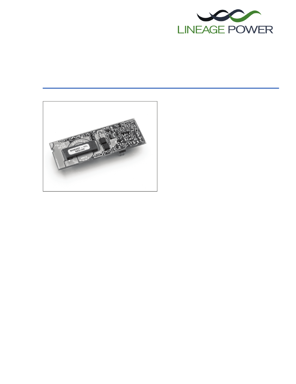
NH033x-L and NH050x-L Series Power Modules:
5 Vdc Input; 1.2 Vdc to 3.3 Vdc Output; 10 A and 15 A
The NH033x-L and NH050x-L Series Power Modules use
advanced, surface-mount technology and deliver high-qual-
ity, compact, dc-dc conversion at an economical price.
Applications
n
Distributed power architectures
n
Servers
n
Workstations
n
Desktop computers
Features
n
Small size: 69.9 mm x 25.4 mm x 8.6 mm
(2.75 in. x 1.00 in. x 0.34 in.)
n
Non-isolated output
n
Constant frequency
n
High efficiency: 91% typical
n
Overcurrent protection
n
Remote on/off
n
Output voltage adjustment:
90% to 110% of V
O, nom
: V
O
Š 2.5 V
100% to 120% of V
O, nom
: V
O
< 2.5 V
n
Overtemperature protection
n
Remote sense
n
UL* 60950 Recognized, CSA
†
C22.2 No. 60950-
00 Certified, VDE 0805 (IEC60950) Licensed
n
Meets FCC Class A radiated limits
Options
n
Tight tolerance output
n
Short pins: 2.79 mm ± 0.25 mm
(0.110 in. ± 0.010 in.)
Description
The NH033x-L and NH050x-L Series Power Modules are non-isolated dc-dc converters that operate over an
input voltage range of 4.5 Vdc to 5.5 Vdc and provide a regulated output between 1.2 V and 3.3 V. The open
frame power modules have a maximum output current rating of 10 A and 15 A, respectively, at typical full-load
efficiencies of 91%.
*
UL is a registered trademark of Underwriters Laboratories, Inc.
†
CSA is a registered trademark of Canadian Standards Association.
Document Outline
- Applications
- Features
- Options
- Description
- Absolute Maximum Ratings
- Electrical Specifications
- General Specifications
- Cleanliness Requirements
- Feature Specifications
- Characteristics Curves
- Figure 1. NH033M-L Input Characteristics, TA = 25 °C
- Figure 2. NH050M-L Input Characteristics, TA = 25 °C
- Figure 3. NH033S1R8-L Input Characteristics, TA = 25 °C
- Figure 4. NH050S1R8-L Input Characteristics, TA = 25 °C
- Figure 5. NH033G-L Input Characteristics, TA = 25 °C
- Figure 6. NH050G-L Input Characteristics, TA = 25 °C
- Figure 7. NH033F-L Input Characteristics, TA = 25 °C
- Figure 8. NH050F-L Input Characteristics, TA = 25 °C
- Figure 9. NH033M-L Current Limit, TA = 25 °C
- Figure 10. NH050M-L Current Limit, TA = 25 °C
- Figure 11. NH033S1R8-L Current Limit, TA = 25 °C
- Figure 12. NH050S1R8-L Current Limit, TA = 25 °C
- Figure 13. NH033G-L Current Limit, TA = 25 °C
- Figure 14. NH050G-L Current Limit, TA = 25 °C
- Figure 15. NH033F-L Current Limit, TA = 25 °C
- Figure 16. NH050F-L Current Limit, TA = 25 °C
- Figure 17. NH033M-L Efficiency, TA = 25 °C
- Figure 18. NH050M-L Efficiency, TA = 25 °C
- Figure 19. NH033S1R8-L Efficiency, TA = 25 °C
- Figure 20. NH050S1R8-L Efficiency, TA = 25 °C
- Figure 21. NH033G-L Efficiency, TA = 25 °C
- Figure 22. NH050G-L Efficiency, TA = 25 °C
- Figure 23. NH033F-L Efficiency, TA = 25 °C
- Figure 24. NH050F-L Efficiency, TA = 25 °C
- Figure 25. NH033M-L Typical Start-Up from Remote On/Off, VI = 5 V, IO = 10 A
- Figure 26. NH050M-L Typical Start-Up from Remote On/Off, VI = 5 V, IO = 15 A
- Figure 27. NH033S1R8-L Typical Start-Up from Remote On/Off, VI = 5 V, IO = 10 A
- Figure 28. NH050S1R8-L Typical Start-Up from Remote On/Off, VI = 5 V, IO = 15 A
- Figure 29. NH033G-L Typical Start-Up from Remote On/Off, VI = 5 V, IO = 10 A
- Figure 30. NH050G-L Typical Start-Up from Remote On/Off, VI = 5 V, IO = 15 A
- Figure 31. NH033F-L Typical Start-Up from Remote On/Off, VI = 5 V, IO = 10 A
- Figure 32. NH050F-L Typical Start-Up from Remote On/Off, VI = 5 V, IO = 15 A
- Test Configurations
- Design Considerations
- Safety Considerations
- Feature Descriptions
- Thermal Considerations
- Figure 40. Thermal Test Setup
- Figure 41. Temperature Measurement Location
- Convection Requirements for Cooling
- Convection Requirements for Cooling (continued)
- Figure 43. NH050M-L Typical Power Dissipation vs. Output Current, TA = 25 °C
- Figure 44. NH033S1R8-L Typical Power Dissipation vs. Output Current, TA = 25 °C
- Figure 45. NH050S1R8-L Typical Power Dissipation vs. Output Current, TA = 25 °C
- Figure 46. NH033G-L Typical Power Dissipation vs. Output Current, TA = 25 °C
- Convection Requirements for Cooling (continued)
- Figure 47. NH050G-L Typical Power Dissipation vs. Output Current, TA = 25 °C
- Figure 48. NH033F-L Typical Power Dissipation vs. Output Current, TA = 25 °C
- Figure 49. NH050F-L Typical Power Dissipation vs. Output Current, TA = 25 °C
- Figure 50. NH033x-L Power Derating vs. Local Ambient Temperature and Air Velocity
- Convection Requirements for Cooling (continued)
- Outline Diagram
- Recommended Hole Pattern
- Ordering Information