On off on, Ups 3, Ups 4 – GE Industrial Solutions LP 33U Series 10 & 20 kVA Installation Guide User Manual
Page 31: Ups 2, Ups 1
Modifications reserved
Page 31/40
OPM_LPS_3UI_10K_20K_1US_V010.doc
Installation Guide LP 33U Series 10 & 20 kVA / S1
UPS 3
OFF
Q1
Q2
ON
OFF
ON
F1 F2
F3
F13 F14
F15
F9 F10
F11
E
E
LPS33U_
010-020_
RPA con
nection_0
1
UPS 4
E
E
UPS 2
LPS33U_
010-020_
RPA con
nection_0
1
OFF
Q1
Q2
F9 F10
F11
UPS 1
ON
OFF
ON
F1 F2
F3
F13 F14
F15
ON
OFF
ON
F1 F2
F3
F13 F14
F15
F9 F10
F11
E
E
LPS33U
_010-020
_RPA con
nection_0
1
OFF
Q1
Q2
LPS33U_
010-020_
RPA con
nection_0
1
OFF
Q1
Q2
ON
OFF
ON
F1 F2
F3
F13 F14
F15
F9 F10
F11
E
E
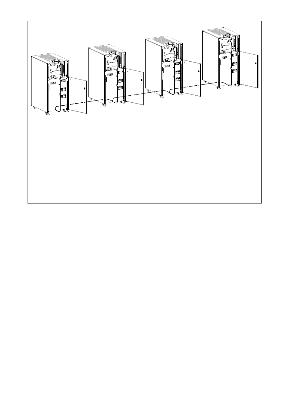
Fig. 3.9.5-4 Control bus location RPA parallel system
Control bus location RPA parallel system
Place the cables and connect them as indicated in the diagram Fig. 3.9.5-4 following these
procedures:
• Fix the control bus cables with the appropriate tie-wrap “E”.
• Place the cables between the parallel units in separated protected conduit to avoid they could
be accidentally interrupted.
• Put in place the front screens “B, C and D” (Fig. 3.9.5-1) paying attention to not damaging the
control bus cables.
It is important to place the units in sequence of their assigned number.
A unit number from 1 to 4, is defined by the setting of parameters and displayed on the control panel.
This number is also marked inside and outside the packaging.
The standard length of the control bus cable between two parallel unit is 26 ft / 8 m.