5 ventilation and cooling, Ventilation and cooling – GE Industrial Solutions LP 33U Series 10 & 20 kVA Installation Guide User Manual
Page 15
Modifications reserved
Page 15/40
OPM_LPS_3UI_10K_20K_1US_V010.doc
Installation Guide LP 33U Series 10 & 20 kVA / S1
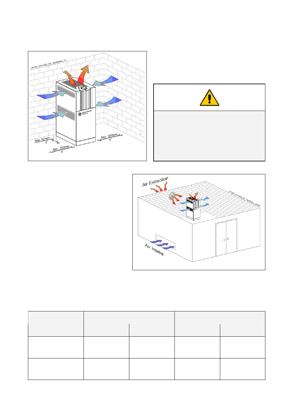
3.5 VENTILATION AND COOLING
The heat produced by the UPS is transferred to the environment by its internal fan(s).
Airflow through the UPS
It is important that the cooling air can freely flow
through the air inlets and outlets of the UPS.
Fig. 3.5-1 Airflow through the LP 33U Series
NOTE !
Insufficient distances on both sides of the
UPS could increase the temperature inside
the UPS.
Do not put any object on the top of the
cabinet: it might obstruct the air flow.
Heat evacuation from UPS room
The heat must be evacuated from the
environment with a proper cooling /
ventilation system provided by the user.
Fig. 3.5-2 Heat evacuation from UPS room
Air volume and losses of the UPS
The below table indicates the heat dissipation at full load at PF = 0.8 lag. and charged battery, up to
3,280 ft (1,000 m) altitude, for cooling air 77°F (25°C) to 86°F (30°C).
Losses
Cooling air flow
UPS model
VFI Mode
ECO Mode
VFI Mode
ECO Mode
LP 33U Series / 10 kVA
3,038 BTU/hr
0.89 kW
546 BTU/hr
0.16 kW
91
CFM
154 m
3
/h
30 CFM
50 m
3
/h
LP 33U Series / 20 kVA
6,075 BTU/hr
1.78 kW
1,092 BTU/hr
0.32 kW
182
CFM
308 m
3
/h
60 CFM
100 m
3
/h