2 dual input utility (option), Dual input utility (option) – GE Industrial Solutions LP 33U Series 10 & 20 kVA Installation Guide User Manual
Page 27
Modifications reserved
Page 27/40
OPM_LPS_3UI_10K_20K_1US_V010.doc
Installation Guide LP 33U Series 10 & 20 kVA / S1
3.9.2
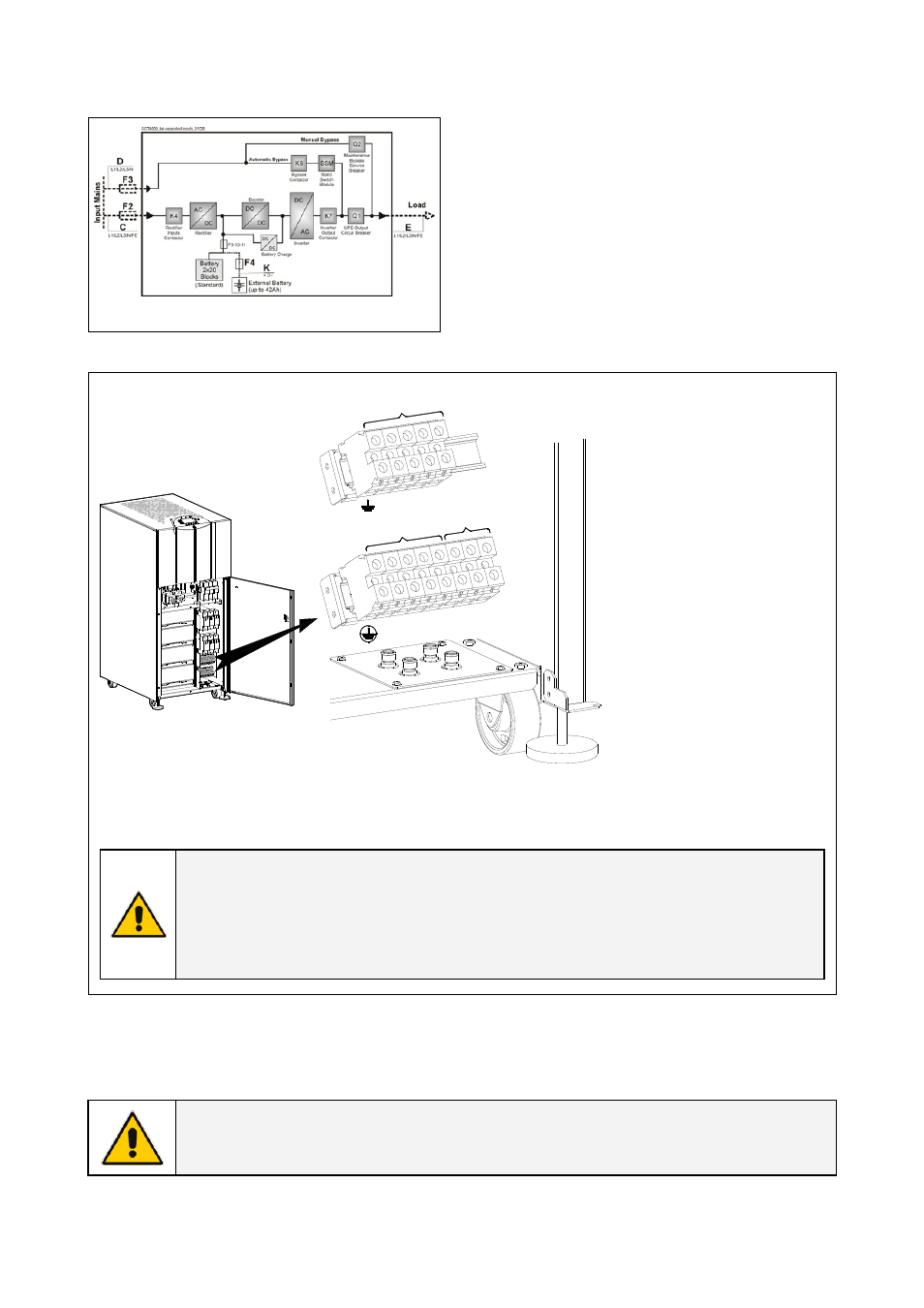
Dual input utility (option)
Fig. 3.9.2-1 Dual input utility (option)
Dual input utility
On request, the UPS can be delivered for dual input
utility.
Two independent lines (F2 and F3) supply
separately the rectifier and the bypass inputs
With this configuration, when the rectifier-input
fuses are opened, the automatic bypass and the
maintenance bypass are supplied by the other line.
OFF
ON
ON
OFF
L1
-1
L2
-1
L3
-1
N1
L1
L2
L3
N2
RECTIF
IER
LOAD
X2
INPUT
1-
BYPAS
S
INPUT
2-
L1
-2
L2
-2
L3
-2
X1
LOAD
LPS33U
_010-020
_Connec
tion com
mon_01
Fig. 3.9.2-2 Power connections Dual Input Utility
Rectifier input utility
L1-1 = Rectifier Phase A
L2-1 = Rectifier Phase B
L3-1 = Rectifier Phase C
N1 =
Neutral
utility
PE =
Earth
Bypass input utility
L1-2 = Bypass Phase A
L2-2 = Bypass Phase B
L3-2 = Bypass Phase C
(N1 = Neutral
utility)
PE =
Earth
Output load
L1 =
Load
phase
A
L2 =
Load
phase
B
L3 =
Load
phase
C
N2 =
Neutral
load
PE =
Earth
load
Max. rating X1 and X2
terminals: 4 AWG (25mm
2
)
NOTE !
For UPS correct operation, the input utility phase rotation must be clock-wise.
Neutral of rectifier input and neutral of bypass input must be coming from the
same input bar.
Inside the UPS, all neutrals N1 and N2 are connected together.
Connect wire to the Terminals using appropriate tools and appropriate torque.
Torque specification for Input / Output and DC power connections on Terminals: Section 3.8.1.
NOTE !
This UPS is designed to operate in a wye-configured electrical system with a solidly
grounded neutral.