GE Industrial Solutions LP 33U Series 10 & 20 kVA Installation Guide User Manual
Page 29
Modifications reserved
Page 29/40
OPM_LPS_3UI_10K_20K_1US_V010.doc
Installation Guide LP 33U Series 10 & 20 kVA / S1
3.9.4
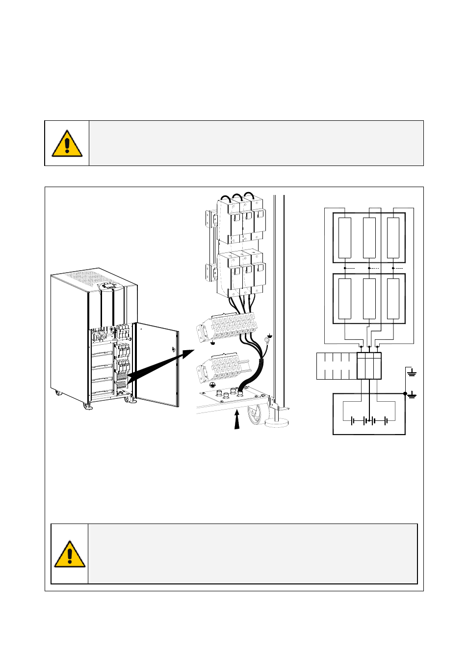
Kit for external battery connection to LP 33U Series / 20 kVA
Before proceeding to an external battery connection, follow the Safety rules concerning the battery.
Make sure that the UPS is not powered, and remove the external battery protections and the fuses F9,
F10, F11 and F13, F14, F15 at the front of the UPS cabinet.
ATTENTION !
Before closing the battery fuses F9, F10, F11 and F13, F14, F15, verify for correct
polarity of the battery connection.
L1
L2
L3
N2
LOAD
X2
X1
L1-1
L2-
1
L3-1
N1
1 - INPU
T UTILI
TY
-
0
+
-
0
+
Bottom entry cables
F9
F10 F1
1
F13 F1
4 F15
X2
LOAD
F9
F10
F11
F13
F14
F15
BATTERY
Red
Re
d
Black
Bla
c
k
Light
Light
b
lue
blue
Battery block diagram
0
+
-
+ 0
-
OFF
OFF
ON
LPS33U_
010-020_
Connectio
n commo
n_01
ON
Fig. 3.9.4-1 Kit for external battery connection to LP 33U Series / 20 kVA
F9 (+)
F13 (+)
= Positive pole
F10 (0)
F14 (0)
=
Central point of
battery blocks
F11 (-)
F15 (-)
= Negative pole
NOTE !
The length of the cables connecting the 3 terminals (X2 - +, 0, -) to the fuses F9, F10,
F11 and F13, F14, F15 must be the same.
Clamp the input battery cables with the included cable-ties.