GE Industrial Solutions AF-300 G11 User Manual
Page 149
13-6
Data subject to change without notice 7/07. © 2007 GE Drives
Name
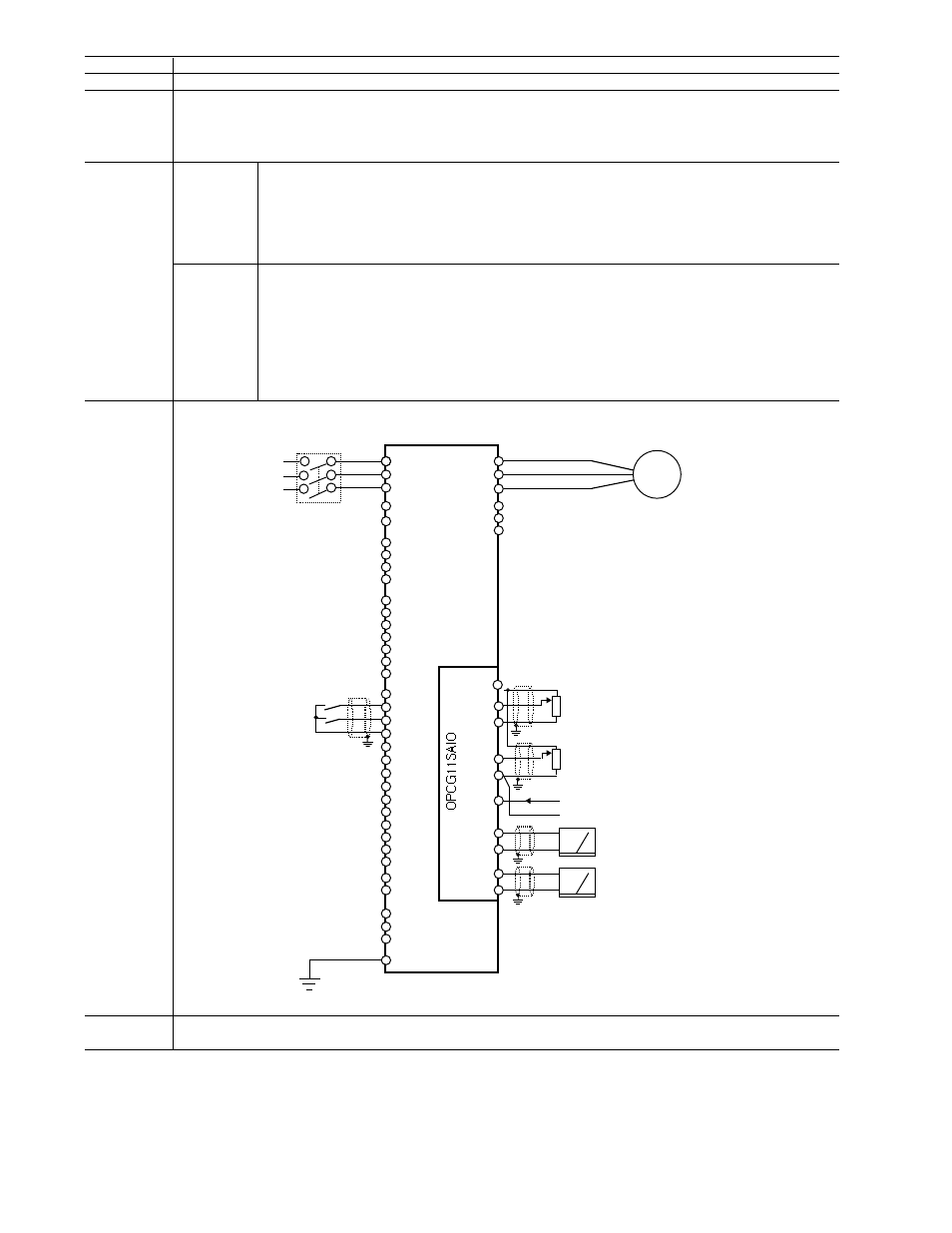
Analog I/O interface card
Type
Function
Specifications Input
Analog signal input (3 points): 32 and 31, 22 and 21, C2 and 21
Terminal 32 - voltage input (both sides):
0 to ±10 Vdc / 0 to ±100%, input impedance: 22k ohm
Terminal 22 - voltage input (both sides):
0 to +10 Vdc / 0 to +100%, input impedance: 22k ohm
4 to + 20 mA dc / 0 to +100%, input impedance: 250k ohm
For voltage input, the power supply terminal for variable resistor (P10) should be connected
Related function code o22
Output
Analog signal output (2 points) between AO+ and AO-, CS+ and CS-
Terminal AO+:
Terminal AO-:
Voltage output common
Terminal CS+:
Current output: 4 to 20 mA dc, max. 500 ohm impedance
Terminal CS-:
Current output common
Terminal CS- is isloated from terminal 21, 31, and AO-
Related function code o23
Connection
Diagram
Remarks
Used to trim operating speed and change torque limit levels using 0-10 Vdc signal, additional voltage, or 4-20 mA output
signal indicating unit's operation (ex. current, frequency, voltage, etc.)
3 analog inputs (2 voltage inputs and 1 current input) to set a torque limiting value (driving, braking), frequency setting, and ratio
setting.
OPCG11SAIO
Voltage output: 0 to ±10 Vdc, for max. 2 voltmeters, input
impedance: 10k ohm
Terminal C2 - current input:
2 analog outputs (1 voltage output and 1 current output): 11 types of data can be output (ref. AF-300 G11/P11
function F30)
X9
X8
X7
X6
X5
X4
X3
X2
X1
E(G)
SD
DX
A
DX
B
FM
P
FM
A
CM
CM
REV
F W
D
PLC
CM
E
AO-
A O+
C2
21
22
31
32
Y 1
Y 2
Y 3
Y 4
Y5C
Y5A
C1
11
12
13
30C
30B
30A
(T0) *
AF-3 0 0G 11
MCCB
or
ELCB
* Te rm i n a ls [ R0 ] an d [ T0] ar e n o t prov id ed f or 1.0 HP or s m a ll e r.
RUN command
input
(R0) *
M
U
V
W
L3/T
L2/S
L1/R
CS+
CS-
(+)
(-)
(+)
VR
VR
(
1k ohm)
(1k ohm)
Voltage input
(Single polarity)
Voltage input
(Both polarity)
Current input
Analog voltmeter
Anammeter