GE Industrial Solutions AF-300 G11 User Manual
Page 147
13-4
Data subject to change without notice 7/07. © 2007 GE Drives
Name
PG feedback card ( AF-300 G11 only)
Type
Function
To perform speed control by detecting motor rotating speed using a pulse generator
Specifications Control
1:1200 (3 to 3600 rpm)
Maximum Speed:
3600 rpm (120 Hz)
Speed Control Accuracy:
±0.02%
Speed Control Response:
40 Hz
Applicable
No. of output pulses:
100 to 3000P/R A/B phase (incremental)
Encoder
Maximum response frequency:
100 kHz
(Generator)
Pulse output method:
Totem pole/open collector. Output current 7 mA or more.
Input Terminal
YA, YB, CM:
YZ, CM:
Output
None
Power Source
1
2
Connection
Diagram
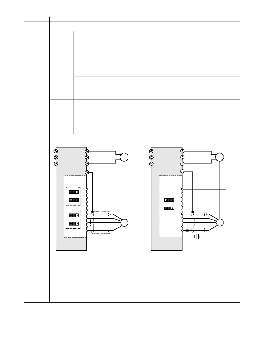
I. Drive Internal Power Supply
II. External Power Supply
Remarks
Internal power source: +15 Vdc ± 10% 120 mA, +12 Vdc ± 10% 120 mA (changeable on PC board
1
) (Terminal:
PO, CM)
Speed Control Range:
OPCG11SPG
Terminals XA, XB and XZ are not in use unless used for a digital reference. They can be used for basic speed control and digital
follower control.
External power source: +12 Vdc (-10%) to +15 Vdc (+1-%) / 300 mA or less
2
(Terminal P1, CM)
Use external power source when more than one PG feedback card is used and the total input current exceeds
120 mA
Connect A- and B-phase output signal from pulse generator on
feedback side
Connect Z-phase output signal from pulse generator on feedback
side. When the pulse generator does not have Z-phase, these
terminals need not be connected.
Take note that the power source matches the specifications of the applied pulse generator
L1 / R
L2/ S
L3 / T
U
V
W
M
PO
XA
XB
XZ
PO
CM
YA
YB
YZ
a)
12VDC
U
V
W
PG
J1
J2
PG
M
1 2 VDC –10%
1 5 VDC –10%
INT
EX T
1 5 V
1 2 V
J1
J2
INT
EXT
b
)
1 5 VDC
J1
J2
G
G
1 5 V 1 2 V
INT
EXT
1 5 V
1 2 V
P I
C M
PO
XA
XB
XZ
PO
CM
YA
YB
YZ
PI
CM
The Jumper J2 can be connected to the 12V or 15V side.
L 1 /R
L 2 /S
L3 /T
P I D
F e e d b a c k
C a r d
P I D
F e e d b a c k
C a r d