GE Industrial Solutions AF-300 G11 User Manual
Page 146
13-3
Data subject to change without notice 7/07. © 2007 GE Drives
Name
Type
Function
To perform speed control by detecting motor rotating speed using a pulse generator
Specifications Control
3 to 3600 rpm (for 4-pole motor)
±0.02%
150% zero-speed (at ZERO signal ON) short time
100 (kp/s)
Applicable
Output Pulse:
20 to 3000 P/R (A, not A, B, not B)
Encoder
PG Power Supply:
+5 Vdc ± 10%/200 mA
(Generator)
Maximum Response Frequency:
100 kHz
Input Terminal
PI:
PG external power supply input
PO:
PG power supply output
CM:
Common
YA:
Input feedback PG phase A (+) pulse
*YA:
Input feedback PG phase A (-) pulse
YB:
Input feedback PG phase B (+) pulse
*YB:
Input feedback PG phase B (-) pulse
Power
Internal Power Supply:
+5 Vdc ± 10%/200 mA
1
Source
External Power Supply:
5 Vdc ± 10%
1
Use an external power supply when 200 mA is exceeded
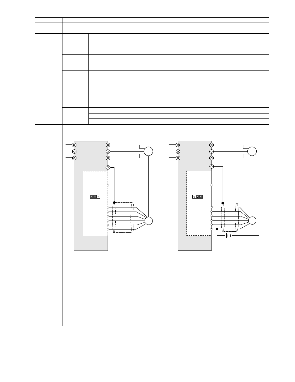
Connection
Diagram
I. Drive Internal Power Supply
II. External Power Supply
Remarks
Speed Control Range:
Speed Control Accuracy:
PG feedback card (AF-300 G11 only)
OPCG11SPG2
Full quadrature speed control with the primary signal and its complement to reduce the effect of electrical noise where required
Starting Torque:
Maximum Number of Input Pulse:
L1/ R
L2 / S
L3 / T
U
V
W
M
YA
P O
* YA
YB
* YB
U
V
W
P G
J1
PG
M
5 Vdc
–10%
INT
EXT
G
G
P I
C M
P I
L1 / R
L2/ S
L3/ T
YA
* YA
YB
* YB
C M
J1
INT
EXT
P O
P I D
F e e d b a c k
C a r d
P I D
F e e d b a c k
C a r d