Safety considerations, Feature descriptions – GE Industrial Solutions Zephyr Non-Isolated SMT User Manual
Page 6
Zephyr Non-Isolated SMT DC-DC Power Module:
0.8V to 3.5V @ 20A Output, 5V to 12V Input
LINEAGE
POWER
6
Data Sheet
March 31, 2010
Safety Considerations
Module’s printed circuit board meets the standards of UL flammability specifications per UL94V-0.
Feature Descriptions
Static Voltage Regulation
The output voltage measured at the converter output pins on the system board will be within the range
shown in Table 3, except during turn-on and turn-off periods. The static limits apply to ambient temperatures
between 0
°C and 70 °C. Static voltage regulation includes:
• DC output initial voltage and set point adjust
• Output load ranges specified in tables above
• Temperature and warm-up input voltage tolerances specified in input voltage and current
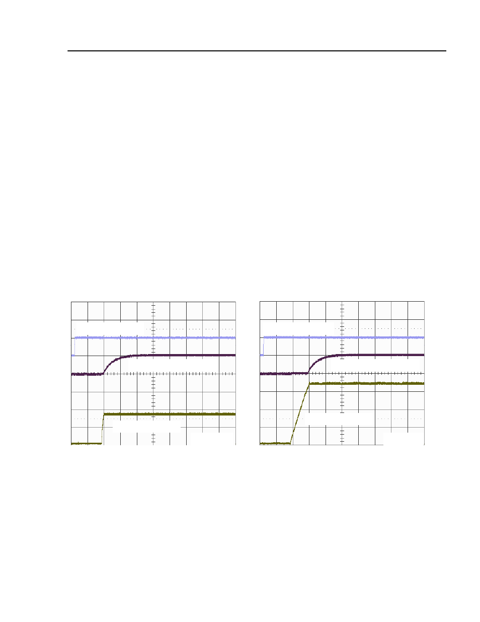
Turn-on Response Time
The output voltage will be within the specified range within 10 ms of the input voltage reaching 90% of its
nominal value with O
UTEN
present. When O
UTEN
is applied with input voltage present, the output voltage will
be inside its specified range within 10 ms. Figure 1 and Figure 2 represent typical start-up waveforms with
the maximum load current and load capacitor on the output indicated in Table 3. A pull-up resistor of 10 k
Ω
is used between Module OK pin and 5V.
O
UTEN
, 5 V/div
O
UTEN
, 5 V/div
M
ODULE
OK, 5 V/div
M
ODULE
OK, 5 V/div
V
OUT
, 1.0 V/div
V
OUT
, 0.5 V/div
2 ms/div
2 ms/div
Figure 1. Turn-on Waveform: V
IN
= 12V,
Figure 2. Turn-on Waveform: V
IN
= 5V,
V
OUT
= 0.8V, 16A resistive load + 10,000
μF
V
OUT
= 3.3V, 16A resistive load + 1,000
μF