General specifications – GE Industrial Solutions Zephyr Non-Isolated SMT User Manual
Page 5
Zephyr Non-Isolated SMT DC-DC Power Module:
0.8V to 3.5V @ 20A Output, 5V to 12V Input
Data Sheet
March 31, 2010
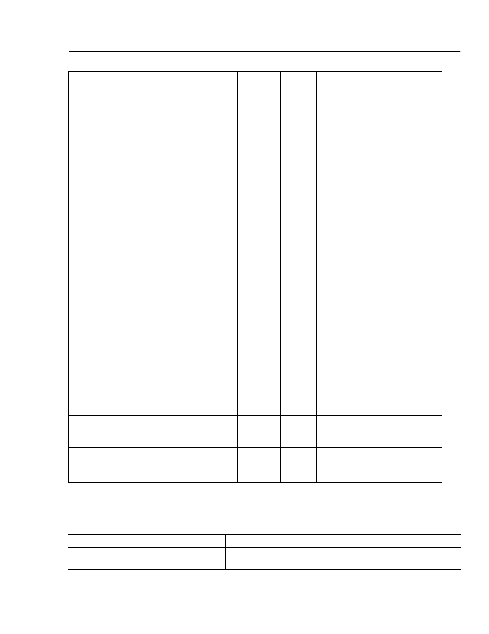
Table 3. Output Specifications (T
A
= 0
°C to 70 °C, V
IN
= 5V to 12V), continued
Efficiency, see Figures 40 – 41
T
A
= 60
°C, 300 LFM, I
OUT
= 16A
• V
OUT
= 2.5V
V
IN
= 12V
V
IN
= 5V
• V
OUT
= 0.8V
V
IN
= 12V
V
IN
= 5V
η
η
η
η
⎯
⎯
⎯
⎯
86
88
71
77
⎯
⎯
⎯
⎯
%
%
%
%
Output Current
Slew Rate
Step function current from I
OUT
= 0A to
16A with no external load capacitors
ΔI
OUT
/
Δt
0
—
600
A/µs
External Load Capacitance
∗
(NOT REQUIRED FOR TRANSIENT RESPONSE)
• V
IN
= 12V
V
OUT
= 0.8V
V
OUT
= 1.3V
V
OUT
= 1.5V
V
OUT
= 1.8V
V
OUT
= 2.0V
V
OUT
= 2.5V
V
OUT
= 3.3V
• V
IN
= 5V
V
OUT
= 0.8V
V
OUT
= 1.3V
V
OUT
= 1.5V
V
OUT
= 1.8V
V
OUT
= 2.0V
V
OUT
= 2.5V
V
OUT
= 3.3V
∗
Maximum capacitance on output into which
module can start with maximum current
C
L
C
L
C
L
C
L
C
L
C
L
C
L
C
L
C
L
C
L
C
L
C
L
C
L
C
L
0
0
0
0
0
0
0
0
0
0
0
0
0
0
—
—
—
—
—
—
—
—
—
—
—
—
—
—
10,000
6,800
3,300
1,000
1,000
1,000
1,000
10,000
10,000
6,800
3,300
3,300
3,300
1,000
μF
μF
μF
μF
μF
μF
μF
μF
μF
μF
μF
μF
μF
μF
Output Current-limit Inception, for I
OUTMAX
at
25
°C, 400 LFM. See thermal derating
curves, Figures 26 – 37
I
OUTLIM
105
⎯
160
% I
OUTMAX
Turn-on Response Time, see Figures 1 – 2
Measured at I
OUT
= 16A and with maximum
external load capacitor as specified above
T
ON
— 5.0 10.0
ms
General Specifications
Table 4. Calculated FIT Rate and Weight
Parameter Min
Typ
Max
Unit
Calculated FIT Rate
—
—
200 Per
10
9
device hours
Weight
—
—
15.5 (0.55)
grams (oz.)
LINEAGE
POWER
5