Fusing considerations, Characteristic – GE Industrial Solutions Zephyr Non-Isolated SMT User Manual
Page 25
Zephyr Non-Isolated SMT DC-DC Power Module:
0.8V to 3.5V @ 20A Output, 5V to 12V Input
LINEAGE
POWER
25
Data Sheet
March 31, 2010
Fusing Considerations
A 10A fuse is required for input voltages of 10.6V and higher. It is not required for input voltages below
10.6V. The following fuse or equivalent is recommended:
Characteristic
Fuse Parameter
Littlefuse R451010 Nano
2
SMF
Fuse Current Rating
10A
10A
Voltage Rating
32 minimum
125
I
2
t 100
a
2
sec maximum
26.4 a
2
sec
DC Interruption Rating
(must be DC rated, not just
AC rated)
35A minimum
35A
UL Recognized
Mandatory
Yes
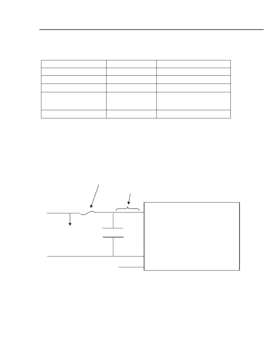
The fuse should be located in the input voltage bus side of the input capacitor to minimize inductance
between the input capacitor and the Zephyr Power Module. The fuse should not be located in proximity to
any object which might abnormally ‘preheat’ the fuse, causing undesired melting.
The Zephyr Power Module begins regulating with an input voltage above approximately 4V and will draw
more input current at lower voltages. If the input voltage rise times and fall times are too slow, shorter fuse
life and nuisance opening may occur. To minimize such fuse input current stresses, the module should be
enabled after input voltage is applied and disabled before input voltage is removed, by using the OUTEN pin.
Fuse, 10A
Minimize this
distance and
inductance
Input
Capacitor
V
IN
-
V
IN
+
Zephyr Module
DC
Input
Bus
To other
modules
or circuits
OUTEN
Figure 47. Fuse Placement