Lineage power 27 – GE Industrial Solutions Zephyr Non-Isolated SMT User Manual
Page 27
Zephyr Non-Isolated SMT DC-DC Power Module:
0.8V to 3.5V @ 20A Output, 5V to 12V Input
Data Sheet
March 31, 2010
R
E
FLOW
TEMP (
°C)
REFLOW TIME (S)
0
50
100
150
200
250
300
P reheat zo ne
max 4
o
Cs
-1
So ak zo ne
30-240s
Heat zo ne
max 4
o
Cs
-1
P eak Temp 235
o
C
Co o ling
zo ne
1-4
o
Cs
-1
T
lim
above
205
o
C
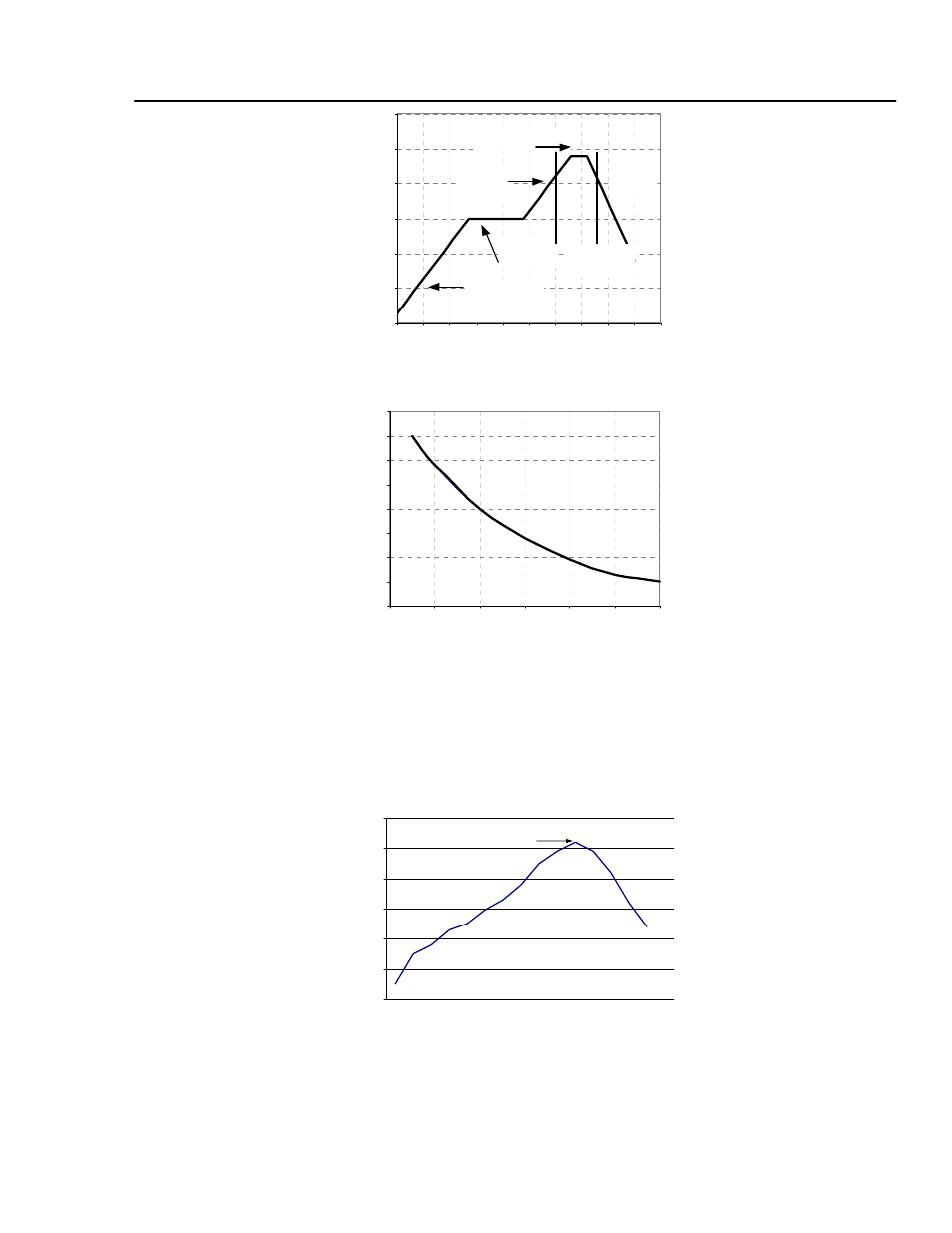
Figure 48. Reflow Profile for Tin/Lead (Sn/Pb) process
MAX TEMP S
O
L
D
ER (
°C)
200
205
210
215
220
225
230
235
240
0
10
20
30
40
50
60
Figure 49. Time Limit Curve Above 205
o
C for Tin/Lead (Sn/Pb) process
Pb-free Reflow Profile
Power Systems will comply with J-STD-020 Rev. C (Moisture/Reflow Sensitivity Classification for
Nonhermetic Solid State Surface Mount Devices) for both Pb-free solder profiles and MSL classification
procedures. This standard provides a recommended forced-air-convection reflow profile based on the
volume and thickness of the package. The suggested Pb-free solder paste is Sn/Ag/Cu (SAC). The
recommended linear reflow profile using Sn/Ag/Cu solder is shown in Fig. 50.
Per J-STD-020 Rev. C
0
50
100
150
200
250
300
Reflow Time (Seconds)
Re
fl
ow T
em
p
(
°C)
Heating Zone
1°C/Second
Peak Temp 260°C
* Min. Time Above 235°C
15 Seconds
*Time Above 217°C
60 Seconds
Cooling
Zone
Figure 50. Recommended linear reflow profile using Sn/Ag/Cu solder.
LINEAGE
POWER
27