20a digital microdlynx, Non-isolated dc-dc power modules, Data sheet – GE Industrial Solutions 20A Digital MicroDLynx User Manual
Page 6: Digital interface specifications
GE
Data Sheet
20A Digital MicroDLynx
TM
: Non-Isolated DC-DC Power Modules
3Vdc –14.4Vdc input; 0.45Vdc to 5.5Vdc output; 20A Output Current
April 24, 2013
©2012 General Electric Company. All rights reserved.
Page 6
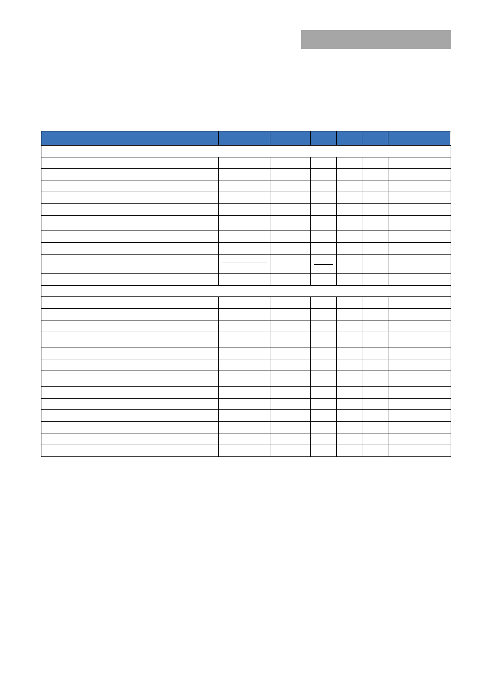
Digital Interface Specifications
Unless otherwise indicated, specifications apply over all operating input voltage, resistive load, and temperature conditions. See
Feature Descriptions for additional information.
Parameter
Conditions
Symbol
Min
Typ
Max
Unit
PMBus Signal Interface Characteristics
Input High Voltage (CLK, DATA)
V
IH
2.1
3.6
V
Input Low Voltage (CLK, DATA)
V
IL
0.8
V
Input high level current (CLK, DATA)
I
IH
-10
10
μA
Input low level current (CLK, DATA)
I
IL
-10
10
μA
Output Low Voltage (CLK, DATA, SMBALERT#)
I
OUT
=2mA
V
OL
0.4
V
Output high level open drain leakage current (DATA,
SMBALERT#)
V
OUT
=3.6V
I
OH
0
10
μA
Pin capacitance
C
O
0.7
pF
PMBus Operating frequency range
Slave Mode
F
PMB
10
400
kHz
Data hold time
Receive Mode
Transmit Mode
t
HD:DAT
0
300
ns
Data setup time
t
SU:DAT
250
ns
Measurement System Characteristics
Read delay time
t
DLY
153
192
231
μs
Output current measurement range
I
RNG
0
26
A
Output current measurement resolution
I
RES
62.5
mA
Output current measurement accuracy at 25°C (with I
OUT,
CORR
)
I
ACC
±5
%
Output current measurement offset
I
OFST
0.1
A
V
OUT
measurement range
V
OUT(rng)
0
5.5
V
V
OUT
measurement resolution
V
OUT(res)
15.62
5
mV
V
OUT
measurement accuracy
V
OUT
,
ACC
-15
5
%
V
OUT
measurement offset
V
OUT(ofst)
-3
3
%
V
IN
measurement range
V
IN(rng)
0
14.4
V
V
IN
measurement resolution
V
IN(res)
32.5
mV
V
IN
measurement accuracy
V
IN, ACC
-15
5
%
V
IN
measurement offset
V
IN(ofst)
-5.5
-2
1.4
LSB