20a digital microdlynx, Non-isolated dc-dc power modules, Data sheet – GE Industrial Solutions 20A Digital MicroDLynx User Manual
Page 20: Trim vout v
GE
Data Sheet
20A Digital MicroDLynx
TM
: Non-Isolated DC-DC Power Modules
3Vdc –14.4Vdc input; 0.45Vdc to 5.5Vdc output; 20A Output Current
April 24, 2013
©2012 General Electric Company. All rights reserved.
Page 20
PU: Sets the default to either operate any time input power
is present or for the ON/OFF to be controlled by the analog
ON/OFF input and the PMBus OPERATION command. This bit
is used together with the CP, CMD and ON bits to determine
startup.
Bit Value
Action
0
Module powers up any time power is
present regardless of state of the analog
ON/OFF pin
1
Module does not power up until
commanded by the analog ON/OFF pin and
the OPERATION command as programmed
in bits [2:0] of the ON_OFF_CONFIG register.
CMD: The CMD bit controls how the device responds to the
OPERATION command.
Bit Value
Action
0
Module ignores the ON bit in the
OPERATION command
1
Module responds to the ON bit in the
OPERATION command
CPR: Sets the response of the analog ON/OFF pin. This bit is
used together with the CMD, PU and ON bits to determine
startup.
Bit Value
Action
0
Module ignores the analog ON/OFF pin, i.e.
ON/OFF is only controlled through the
PMBUS via the OPERATION command
1
Module requires the analog ON/OFF pin to
be asserted to start the unit
PMBus Adjustable Soft Start Rise Time
The soft start rise time can be adjusted in the module via
PMBus. When setting this parameter, make sure that the
charging current for output capacitors can be delivered by
the module in addition to any load current to avoid nuisance
tripping of the overcurrent protection circuitry during
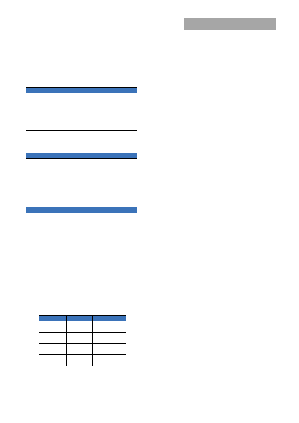
startup. The TON_RISE command sets the rise time in ms,
and allows choosing soft start times between 600μs and
9ms, with possible values listed in Table 5. Note that the
exponent is fixed at -4 (decimal) and the upper two bits of
the mantissa are also fixed at 0.
Table 5
Rise Time
Exponent
Mantissa
600μs
11100
00000001010
900μs
11100
00000001110
1.2ms
11100
00000010011
1.8ms
11100
00000011101
2.7ms
11100
00000101011
4.2ms
11100
00001000011
6.0ms
11100
00001100000
9.0ms
11100
00010010000
Output Voltage Adjustment Using the PMBus
The VOUT_SCALE_LOOP parameter is important for a
number of PMBus commands related to output voltage
trimming, margining, over/under voltage protection and the
PGOOD thresholds. The output voltage of the module is set
as the combination of the voltage divider formed by RTrim
and a 20kΩ upper divider resistor inside the module, and the
internal reference voltage of the module. The reference
voltage V
REF
is nominally set at 600mV, and the output
regulation voltage is then given by
REF
OUT
V
RTrim
RTrim
V
20000
Hence the module output voltage is dependent on the value
of RTrim which is connected external to the module. The
information on the output voltage divider ratio is conveyed
to the module through the VOUT_SCALE_LOOP parameter
which is calculated as follows:
RTrim
RTrim
LOOP
SCALE
VOUT
20000
_
_
The VOUT_SCALE_LOOP parameter is specified using the
“Linear” format and two bytes. The upper five bits [7:3] of the
high byte are used to set the exponent which is fixed at –9
(decimal). The remaining three bits of the high byte [2:0] and
the eight bits of the lower byte are used for the mantissa.
The default value of the mantissa is 00100000000
corresponding to 256 (decimal), corresponding to a divider
ratio of 0.5. The maximum value of the mantissa is 512
corresponding to a divider ratio of 1. Note that the
resolution of the VOUT_SCALE_LOOP command is 0.2%.
When PMBus commands are used to trim or margin the
output voltage, the value of V
REF
is what is changed inside
the module, which in turn changes the regulated output
voltage of the module.
The nominal output voltage of the module can be adjusted
with a minimum step size of 0.4% over a ±25% range from
nominal using the VOUT_TRIM command over the PMBus.
The VOUT_TRIM command is used to apply a fixed offset
voltage to the output voltage command value
using the “Linear” mode with the exponent fixed at –10
(decimal). The value of the offset voltage is given by
10
)
(
2
_
TRIM
VOUT
V
offset
OUT
This offset voltage is added to the voltage set through the
divider ratio and nominal V
REF
to produce the trimmed
output voltage. The valid range in two’s complement for this
command is –4000h to 3999h. The high order two bits of
the high byte must both be either 0 or 1. If a value outside of
the +/-25% adjustment range is given with this command,
the module will set it’s output voltage to the nominal value
(as if VOUT_TRIM had been set to 0), assert SMBALRT#, set
the CML bit in STATUS_BYTE and the invalid data bit in
STATUS_CML.