20a digital microdlynx, Non-isolated dc-dc power modules, Data sheet – GE Industrial Solutions 20A Digital MicroDLynx User Manual
Page 17
GE
Data Sheet
20A Digital MicroDLynx
TM
: Non-Isolated DC-DC Power Modules
3Vdc –14.4Vdc input; 0.45Vdc to 5.5Vdc output; 20A Output Current
April 24, 2013
©2012 General Electric Company. All rights reserved.
Page 17
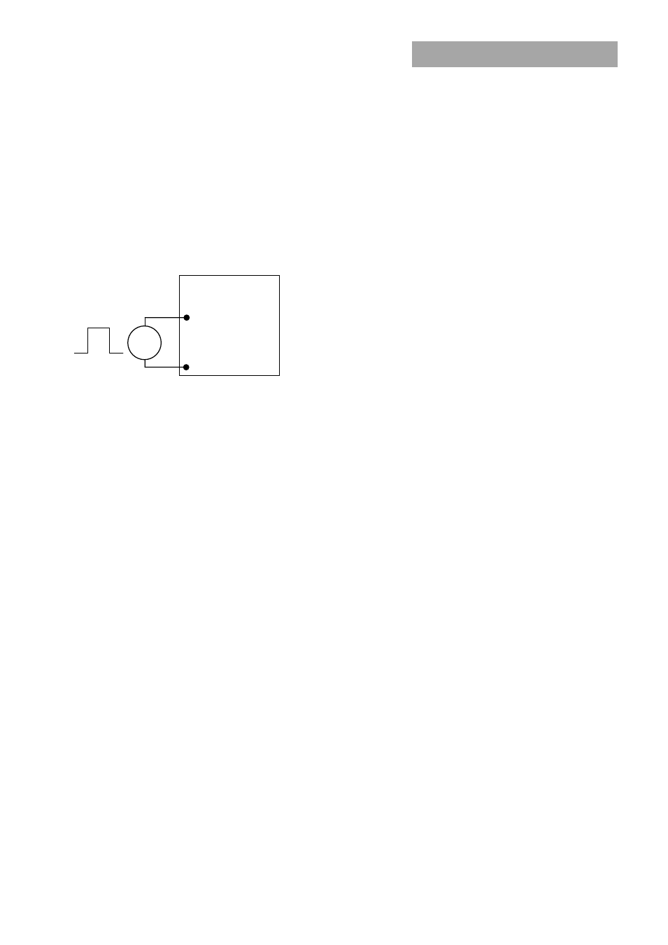
Synchronization
The module switching frequency can be synchronized to a
signal with an external frequency within a specified range.
Synchronization can be done by using the external signal
applied to the SYNC pin of the module as shown in Fig. 45,
with the converter being synchronized by the rising edge of
the external signal. The Electrical Specifications table
specifies the requirements of the external SYNC signal. If the
SYNC pin is not used, the module should free run at the
default switching frequency. If synchronization is not being
used, connect the SYNC pin to GND.
MODULE
SYNC
GND
+
─
Figure 45. External source connections to synchronize
switching frequency of the module.
Measuring Output Current, Output Voltage and
Input Voltage
Please see the Digital Feature Descriptions section.
Dual Layout
Identical dimensions and pin layout of Analog and Digital
MicroDLynx modules permit migration from one to the other
without needing to change the layout. In both cases the trim
resistor is connected between trim and signal ground. The
output of the analog module cannot be trimmed down to
0.45V
Power Good
The module provides a Power Good (PGOOD) signal that is
implemented with an open-drain output to indicate that the
output voltage is within the regulation limits of the power
module. The PGOOD signal will be de-asserted to a low state
if any condition such as overtemperature, overcurrent or
loss of regulation occurs that would result in the output
voltage going ±10% outside the setpoint value. The PGOOD
terminal can be connected through a pullup resistor
(suggested value 100K
) to a source of 5VDC or lower.