20a digital microdlynx, Non-isolated dc-dc power modules, Data sheet – GE Industrial Solutions 20A Digital MicroDLynx User Manual
Page 19: Digital feature descriptions
GE
Data Sheet
20A Digital MicroDLynx
TM
: Non-Isolated DC-DC Power Modules
3Vdc –14.4Vdc input; 0.45Vdc to 5.5Vdc output; 20A Output Current
April 24, 2013
©2012 General Electric Company. All rights reserved.
Page 19
Digital Feature Descriptions
PMBus Interface Capability
The 20A Digital MicroDLynx
TM
power modules have a PMBus
interface that supports both communication and control.
The PMBus Power Management Protocol Specification can
be obtained from
The modules support a
subset of version 1.1 of the specification (see Table 6 for a
list of the specific commands supported). Most module
parameters can be programmed using PMBus and stored as
defaults for later use.
All communication over the module PMBus interface must
support the Packet Error Checking (PEC) scheme. The PMBus
master must generate the correct PEC byte for all
transactions, and check the PEC byte returned by the
module.
The module also supports the SMBALERT# response
protocol whereby the module can alert the bus master if it
wants to talk. For more information on the SMBus alert
response protocol, see the System Management Bus
(SMBus) specification.
The module has non-volatile memory that is used to store
configuration settings. Not all settings programmed into the
device are automatically saved into this non-volatile
memory, only those specifically identified as capable of
being stored can be saved (see Table 6 for which command
parameters can be saved to non-volatile storage).
PMBus Data Format
For commands that set thresholds, voltages or report such
quantities, the module supports the “Linear” data format
among the three data formats supported by PMBus. The
Linear Data Format is a two byte value with an 11-bit, two’s
complement mantissa and a 5-bit, two’s complement
exponent. The format of the two data bytes is shown below:
Data Byte High
7 6 5 4 3
2 1 0 7 6 5 4 3 2 1 0
Data Byte Low
Exponent
MSB
Mantissa
MSB
The value is of the number is then given by
Value = Mantissa x 2
Exponent
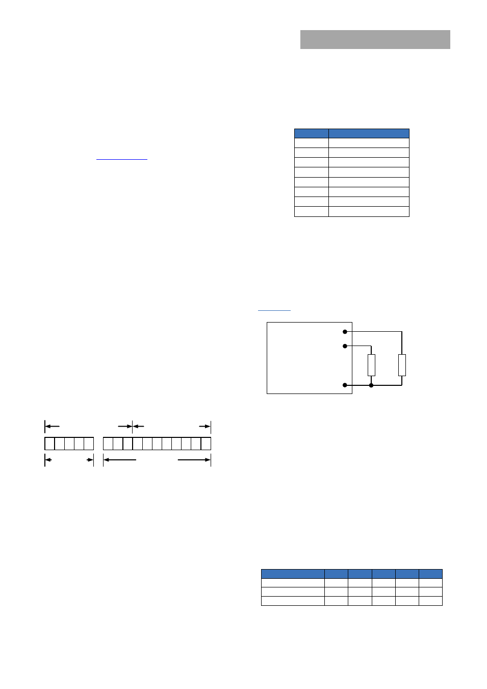
PMBus Addressing
The power module can be addressed through the PMBus
using a device address. The module has 64 possible
addresses (0 to 63 in decimal) which can be set using
resistors connected from the ADDR0 and ADDR1 pins to
GND. Note that some of these addresses (0, 1, 2, 3, 4, 5, 6, 7,
8, 9, 10, 11 12, 40, 44, 45, 55 in decimal) are reserved
according to the SMBus specifications and may not be
useable. The address is set in the form of two octal (0 to 7)
digits, with each pin setting one digit. The ADDR1 pin sets
the high order digit and ADDR0 sets the low order digit. The
resistor values suggested for each digit are shown in Table 4
(1% tolerance resistors are recommended). Note that if
either address resistor value is outside the range specified in
Table 4, the module will respond to address 127.
Table 4
Digit
Resistor Value (KΩ)
0
10
1
15.4
2
23.7
3
36.5
4
54.9
5
84.5
6
130
7
200
The user must know which I
2
C addresses are reserved in a
system for special functions and set the address of the
module to avoid interfering with other system operations.
Both 100kHz and 400kHz bus speeds are supported by the
module. Connection for the PMBus interface should follow
the High Power DC specifications given in section 3.1.3 in the
SMBus specification V2.0 for the 400kHz bus speed or the
Low Power DC specifications in section 3.1.2. The complete
SMBus specification is available from the SMBus web site,
smbus.org.
ADDR0
SIG_GND
R
ADDR0
R
ADDR1
ADDR1
Figure 47. Circuit showing connection of resistors used to
set the PMBus address of the module.
PMBus Enabled On/Off
The module can also be turned on and off via the PMBus
interface. The OPERATION command is used to actually turn
the module on and off via the PMBus, while the
ON_OFF_CONFIG command configures the combination of
analog ON/OFF pin input and PMBus commands needed to
turn the module on and off. Bit [7] in the OPERATION
command data byte enables the module, with the following
functions:
0
:
Output is disabled
1
:
Output is enabled
This module uses the lower five bits of the ON_OFF_CONFIG
data byte to set various ON/OFF options as follows:
Bit Position
4
3
2
1
0
Access
r/w
r/w
r/w
r/w
r
Function
PU
CMD CPR
POL
CPA
Default Value
1
0
1
1
1