Pim400 series; atca board power input modules, Preliminary data sheet, Pim400 internal block diagram – GE Industrial Solutions PIM400 Series User Manual
Page 11: Pin functions
GE
Preliminary Data Sheet
PIM400 Series; ATCA Board Power Input Modules
-36 to -75 Vdc; 400W/10A
June 20, 2013
©2013 General Electric Company. All rights reserved.
Page 11
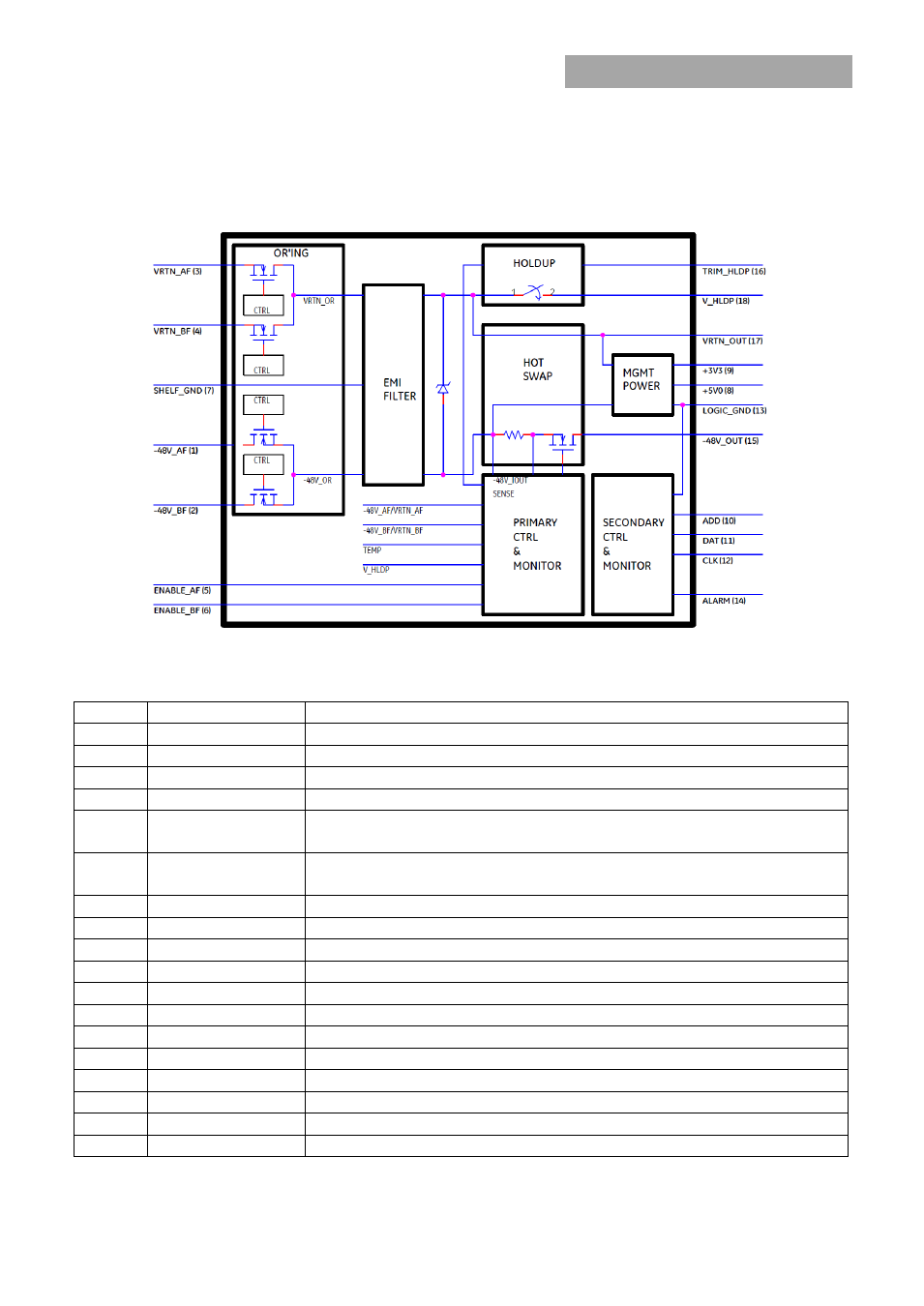
PIM400 Internal Block Diagram
PIN FUNCTIONS
Pin No.
Signal Name
Description
1
-48V_AF
-48V_A Feed (Externally Fused)
2
-48V_BF
-48V_B Feed (Externally Fused)
3
VRTN_AF
VRTN_A Feed (Externally Fused)
4
VRTN_BF
VRTN_B Feed (Externally Fused)
5
ENABLE_AF
ENABLE_A Feed (Externally Fused)
(Short Pin, connected to VRTN_A on the back plane)
6
ENABLE_BF
ENABLE_B Feed (Externally Fused)
(Short Pin, connected to VRTN_B on the back plane)
7
SHELF_GND
Shelf / Chassis / Safety Ground
8
+5V0
Isolated 5.0Vdc (Blue LED Power) w.r.t. LOGIC_GND
9
+3V3
Isolated 3.3Vdc (Management Power) w.r.t. LOGIC_GND
10*
ADD
I2C Address w.r.t. LOGIC_GND
11*
DAT
I2C Data w.r.t. LOGIC_GND
12*
CLK
I2C Clock w.r.t. LOGIC_GND
13
LOGIC_GND
Logic / Secondary / Isolated Ground
14
ALARM
Opto-isolated -48V A/B Feed Loss or Open Fuse Alarm (w.r.t LOGIC_GND)
15
-48V_OUT
OR’d and Inrush protected –48V Output Bus
16
TRIM_HLDP
Holdup capacitor output voltage trim w.r.t. -48V_OUT
17
VRTN_OUT
OR’d and Inrush protected VRTN Output Bus
18
V_HLDP
+ve terminal connection point for Holdup capacitor
* Pins 10, 11 & 12 are present only on modules with I
2
C digital interface option (-K)