GE Industrial Solutions LP 33U Series 10 & 20 kVA Operating Manual User Manual
Page 60
Modifications reserved
Page 60/63
OPM_LPS_3UO_10K_20K_1US_V010.doc
Operating Manual LP 33U Series 10 & 20 kVA / S1
7.2.8 Restore to normal operation after “EPO – Emergency Power Off”
NOTE !
Make sure the all units of the Parallel System to be status of the activation of “EPO -
Emergency Power Off”, i. e. Q1 closed, Q2 open and the “Rectifier input fuses - F1, F2,
F3” and “Battery fuses - F9, F10, F11 / F13, F14, F15” connected.
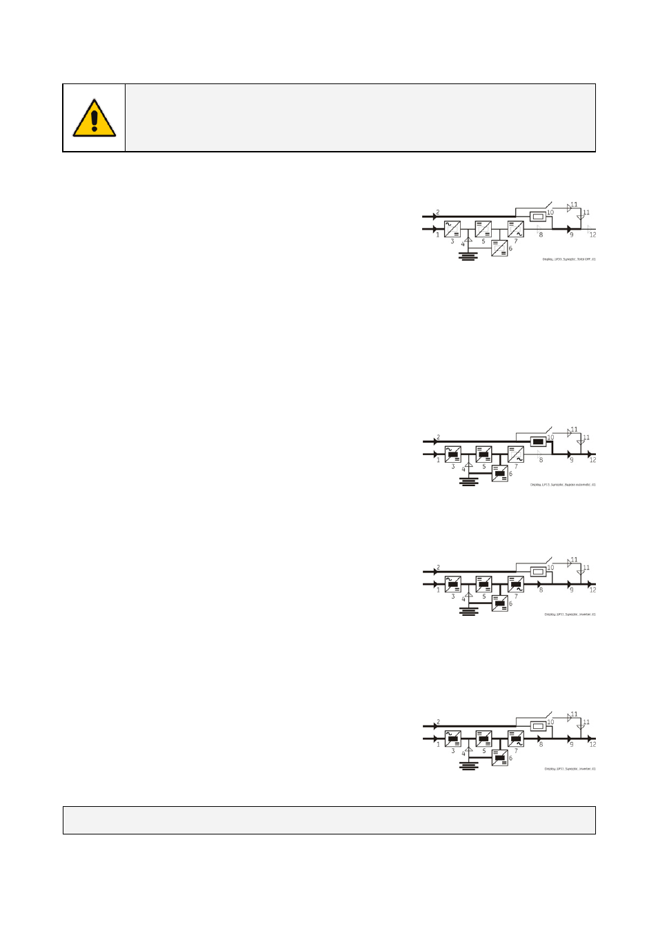
View of the synoptic diagram, on all UPS units, after pressing
the push-button “EPO - Emergency Power Off”:
• All Contactors are open.
• Booster, Inverter and Static-Switch shutdown.
1. Reset
the
push-button “EPO”.
Press MUTE key to reset Alarm and Acoustical alarm.
LED Alarm remains lit.
2. Reset the UPS by pressing “Inverter OFF” ( O ) key on all UPS units.
The load is supplied by the utility through the automatic bypass.
The booster starts automatically.
The synoptic diagram must display the status “LOAD SUPPLIED BY
AUTOMATIC BYPASS”.
3. Insert the inverter by pressing “Inverter ON” ( I ) key on first UPS unit.
In case of sufficient output power, the output will transfer to
Inverter.
LED Alarm turn Off and the LED Operation must be is lit.
The Synoptic diagram, on first UPS unit, must display the status
“LOAD SUPPLIED BY INVERTER”.
4. Insert the inverter by pressing “Inverter ON” ( I ) key on all other UPS units.
Do not start the next inverter until the sequence of the previous one end.
As soon as the output power of the inverters is sufficient to supply the load, the output of the units with
running inverter will transfer to inverter.
LED Alarm turn Off and the LED Operation must be lit.
The Synoptic diagram, on all UPS units, must display the status
“LOAD SUPPLIED BY INVERTER”.
END OF PROCEDURE