GE Industrial Solutions LP 33U Series 10 & 20 kVA Operating Manual User Manual
Page 44
Modifications reserved
Page 44/63
OPM_LPS_3UO_10K_20K_1US_V010.doc
Operating Manual LP 33U Series 10 & 20 kVA / S1
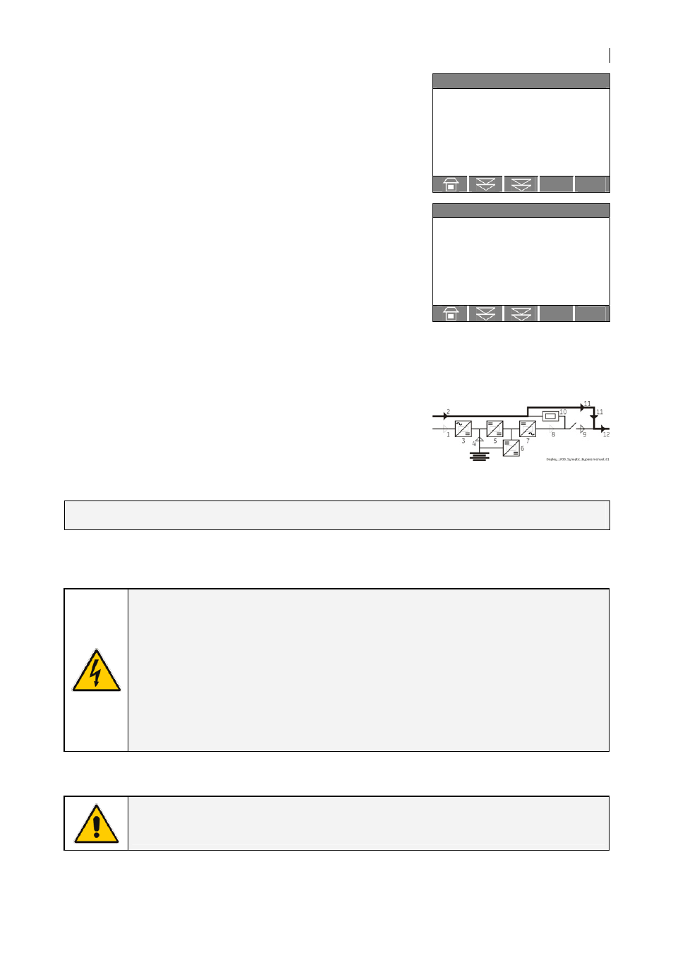
6. In order to discharge the DC link capacitors, insert the inverter by pressing “Inverter ON” ( I ) key.
`
Home\Meter
INVERTER
f :
60.0
Hz
L1 :
7
V
L2 :
7
V
L3 :
7
V
T :
OK
SYNCHRONIZED
Remark:
Command INVERTER ON will be enabled only when the inverter
voltage of each phase decreases below 7 Vac (about 30 seconds).
`
Home\Meter
BOOSTER
f :
60.0
Hz
L1 :
120
V
L2 :
120
V
L3 :
120
V
Vp :
5
V
Vn :
5
V
Before proceeding to step 7, check on the display panel that the DC
link voltage (both polarities) Vp and Vn has reached the max.
voltage of 5 Vdc (about 30 seconds).
The acoustical alarm is activated, press “MUTE” key (from Home
screen) to reset it.
7. Disconnect the inverter by pressing “Inverter OFF” ( O ) key and hold until the LED inverter (7)
turns OFF.
The load is now powered directly by utility through the
MANUAL BYPASS Q2.
END OF PROCEDURE
WARNING !
If the above procedure is not completely performed, it could cause
serious damages to the UPS.
In case the procedure described on step “6 - Discharge DC link capacitors” cannot
be completely performed, the DC capacitors could be charged with dangerous
voltage for a minimum of 5 minutes.
Wait until capacitors are completely discharged before starting the UPS again.
The UPS cabinet contains parts electrically live.
Apart from the front door, do not open any other part of the UPS.
NOTE !
With separate utility inputs, it’s possible to disconnect utility rectifier.