2 procedures for lp 33u series parallel system, 1 lp 33u series parallel system start-up, Procedures for lp 33u series parallel system – GE Industrial Solutions LP 33U Series 10 & 20 kVA Operating Manual User Manual
Page 49: Lp 33u series parallel system start-up, Warning
Modifications reserved
Page 49/63
OPM_LPS_3UO_10K_20K_1US_V010.doc
Operating Manual LP 33U Series 10 & 20 kVA / S1
7.2 PROCEDURES FOR LP 33U Series PARALLEL SYSTEM
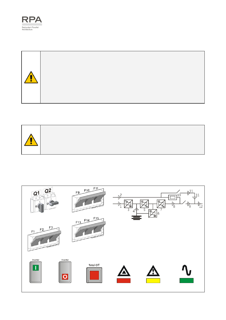
7.2.1 LP 33U Series Parallel System start-up
WARNING
!
Before connecting hazardous voltages, make sure that:
• The connection to the electrical system has been performed by qualified personnel;
• The equipment frame has been correctly grounded to the main earth;
• Make sure that utility input protection is removed;
• All the panels removed to allow the UPS connection have been correctly reinstalled;
• The UPS switches Q1 and Q2 are OFF (Pos. 0);
• The input fuses rectifier F1, F2, F3 and battery fuses F9, F10, F11 / F13, F14, F15 are
removed.
This procedure must be performed for the first start-up following the installation, with all the UPS units
completely switched Off and not powered.
This procedure presupposes that the load is not yet supplied by the UPS Parallel System.
NOTE !
The UPS Parallel System can be started-up using the battery supply in case the input
utility should be unavailable.
To avoid an incidental battery discharge, it is recommended to proceed to the UPS
Parallel System start-up having the input utility available.
Open the front door on all UPS units and make sure that:
•
All the connections to the input/output terminals of the UPS have been made correctly.
•
The safety screens are fixed in their position.
•
The switches Q1 and Q2 are open (Pos. O) and the “Rectifier input fuses - F1, F2, F3” and “Battery
fuses - F9, F10, F11 / F13, F14, F15” are removed.
Q1 UPS output switch
Q2 Manual
bypass
switch
LEDs on synoptic diagram
LED 1 Utility rectifier OK
LED 2 Utility bypass OK
LED 3 Rectifier ON
LED 4 Discharging battery
LED 5 Booster ON
LED 6 Charge battery ON
LED 7
Inverter available
LED 8
Inverter ON
LED 9
Q1 closed
LED 10 Automatic bypass ON
LED 11 Manual bypass Q2 ON
LED 12 Load on UPS
Input fuses rectifier
Battery fuses
(F13-F14-F15 are only for
LP 33U series / 20 kVA)
Key Key Key LED LED LED
Inverter ON
Inverter OFF
Total Off
Stop Operation
Alarm
Operation
Continue ►