3 from manual bypass q2 to normal function vfi, From manual bypass q2 to normal function vfi – GE Industrial Solutions LP 33U Series 10 & 20 kVA Operating Manual User Manual
Page 45
Modifications reserved
Page 45/63
OPM_LPS_3UO_10K_20K_1US_V010.doc
Operating Manual LP 33U Series 10 & 20 kVA / S1
7.1.3 From Manual Bypass Q2 to normal function VFI
This procedure presupposes that the load is powered by the manual bypass switch, and:
• The inverter is switched OFF;
• The manual bypass switch Q2 is closed (Pos. I);
• The output switch Q1 is open (Pos. 0);
• The “rectifier input fuses - F1, F2, F3” and “battery fuses - F9, F10, F11/ F13, F14, F15” are removed;
• LED Alarm blinks.
NOTE !
This procedure must not be performed if the UPS is used as frequency converter.
1. Insert the “rectifier input fuses - F1, F2, F3” and the “battery fuses - F9, F10, F11 / F13, F14, F15”
(insert the external battery fuses in case of external battery).
2. Close the output switch Q1 (Pos. I).
Load is now supplied parallel through automatic bypass and
manual bypass Q2.
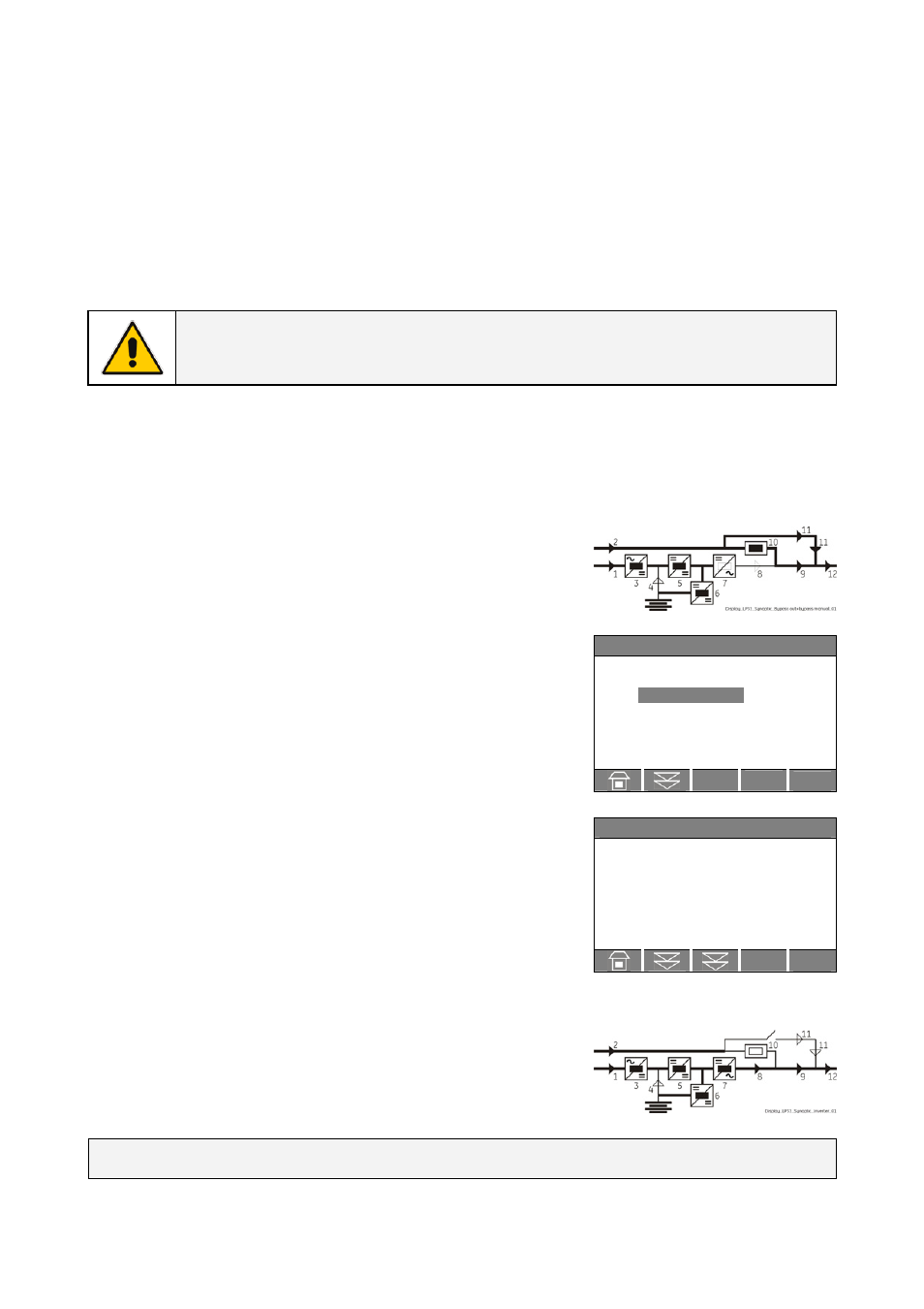
The synoptic diagram must display the status “LOAD SUPPLIED BY
AUTOMATIC BYPASS AND MANUAL BYPASS Q2”.
`
Home\Commands
COMMANDS
RESET TOTAL OFF
REQUEST TOTAL OFF
3. Only in case it has been previously activated, restore the
command “Total Off” by entering the screen:
COMMANDS/RESET TOTAL OFF
V
`
Home\Meter
BOOSTER
f :
60.0
Hz
L1 :
120
V
L2 :
120
V
L3 :
120
V
Vp :
215
V
Vn :
215
V
4. Open the manual bypass switch Q2 (Pos. 0).
The load is supplied by the utility through the automatic bypass.
Verify, selecting the screen METERING/BOOSTER/Vp and Vn, that the
booster voltage has reached about 215 Vdc.
5. Insert the inverter by pressing “Inverter ON” ( I ) key.
Some seconds later the load will be transferred on inverter.
LED Alarm turn Off and the LED Operation must be lit.
The synoptic diagram must display the status “LOAD SUPPLIED BY
INVERTER”.
END OF PROCEDURE