High power service manual for unit sizes 6x – GE Industrial Solutions AF-600 FP High Power Unit Sizes 6x User Manual
Page 133
Pin No. Schematic
Acronym
Function
Description
Reading Using a Digital Voltmeter
18
HI_LOW
Control signal from
Power Card
Signal to switch fan speeds between high and low
+5VDC = fans on high,
Otherwise, 0VDC.
19
SCR_DIS
Control signal for SCR
front end
Indicates SCR front end is enabled or disabled.
0.6 to 0.8 VDC – SCRs enabled
0VDC – SCR disabled
20
INV_DIS
Control signal from
Power Card
Disables IGBT gate voltages
5VDC – inverter disabled
0VDC – inverter enabled
21
Not
used
22
UINVEX
Bus Voltage scaled
down
Signal proportional to UDC
OV switch must be off
- 1 VDC = 450 VDC [T4/T5]
- 1 VDC = 610 VDC [T7]
23
VDD
+24 VDC power supply
Yellow LED indicates voltage is present.
+24 VDC regulated supply
+23 to 25 VDC
24
VCC
+5.0 VDC regulated sup-
ply. +4.75-5.25 VDC
The green LED indicates voltage is present.
+5.0 VDC regulated supply +4.75 to 5.25 VDC
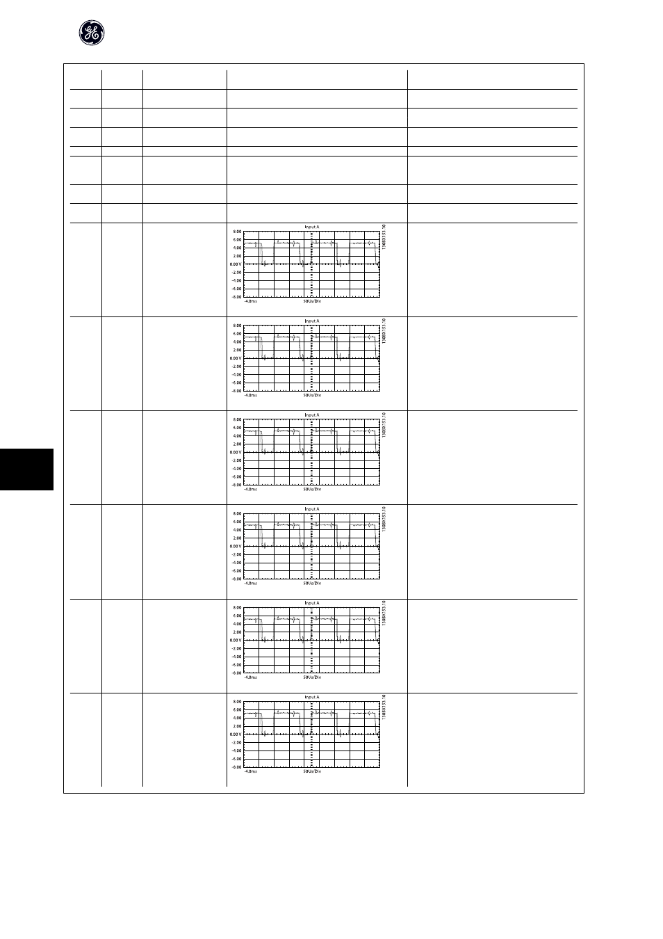
25
GUP_T
IGBT gate signal, buf-
fered, U phase, positive.
Signal originates on
Control Card.
2v/div 100us/div Run
@10Hz
2.2–2.5 VDC
Equal on all phases
TP25-TP30
26
GUN_T
IGBT gate signal, buf-
fered, U phase, negative.
Signal originates on
Control Card.
2v/div 100us/div Run
@10Hz
2.2–2.5 VDC
Equal on all phases
TP25-TP30
27
GVP_T
IGBT gate signal, buf-
fered, V phase, positive.
Signal originates on
Control Card.
2v/div 100us/div Run
@10Hz
2.2–2.5 VDC
Equal on all phases
TP25-TP30
28
GVN_T
IGBT gate signal, buf-
fered, V phase, negative.
Signal originates on
Control Card.
2v/div 100us/div Run
@10Hz
2.2–2.5 VDC
Equal on all phases
TP25-TP30
29
GWP_T
IGBT gate signal, buf-
fered, W phase, positive.
Signal originates on
Control Card.
2v/div 100us/div Run
@10Hz
2.2–2.5 VDC
Equal on all phases
TP25-TP30
30
GWN_T
IGBT gate signal, buf-
fered, W phase, nega-
tive. Signal originates on
Control Card.
2v/div 100us/div Run
@10Hz
2.2–2.5 VDC
Equal on all phases TP25-TP30
High Power Service Manual for Unit Sizes 6x
132
10