Module – GE Industrial Solutions 12V Mega TLynx User Manual
Page 14
Data Sheet
May 4, 2012
12V Mega TLynx
TM
: Non-Isolated DC-DC Power Modules:
6.0 – 14Vdc Input; 0.8Vdc to 3.63Vdc Output; 30A output
current
LINEAGE
POWER
14
Good layout techniques should be observed when
using multiple units in parallel. To implement forced
load sharing, the following connections should be
made:
• The share pins of all units in parallel must be
connected together. The path of these
connections should be as direct as possible.
• All remote-sense pins should be connected to
the power bus at the same point, i.e., connect
all the SENSE
(+)
pins to the
(+)
side of the bus.
Close proximity and directness are necessary
for good noise immunity
Some special considerations apply for design of
converters in parallel operation:
• When sizing the number of modules required
for parallel operation, take note of the fact that
current sharing has some tolerance. In
addition, under transient condtions such as a
dynamic load change and during startup, all
converter output currents will not be equal. To
allow for such variation and avoid the likelihood
of a converter shutting off due to a current
overload, the total capacity of the paralleled
system should be no more than 75% of the
sum of the individual converters. As an
example, for a system of four 12V Mega
TLynx
TM
converters in parallel, the total current
drawn should be less that 75% of (4 x 30A) ,
i.e. less than 90A.
• All modules should be turned on and off
together. This is so that all modules come up at
the same time avoiding the problem of one
converter sourcing current into the other
leading to an overcurrent trip condition. To
ensure that all modules come up
simultaneously, the on/off pins of all paralleled
converters should be tied together and the
converters enabled and disabled using the
on/off pin.
• The share bus is not designed for redundant
operation and the system will be non-functional
upon failure of one of the unit when multiple
units are in parallel. In particular, if one of the
converters shuts down during operation, the
other converters may also shut down due to
their outputs hitting current limit. In such a
situation, unless a coordinated restart is
ensured, the system may never properly restart
since different converters will try to restart at
different times causing an overload condition
and subsequent shutdown. This situation can
be avoided by having an external output
voltage monitor circuit that detects a shutdown
condition and forces all converters to shut
down and restart together.
When not using the active load sharing feature,
share pins should be left unconnected.
Tunable Loop
TM
The 12V Mega TLynx
TM
modules have a new
feature that optimizes transient response of the
module called Tunable Loop
TM
.
External capacitors are usually added to the output
of the module for two reasons: to reduce output
ripple and noise (see Fig. 29) and to reduce output
voltage deviations from the steady-state value in the
presence of dynamic load current changes. Adding
external capacitance however affects the voltage
control loop of the module, typically causing the
loop to slow down with sluggish response. Larger
values of external capacitance could also cause the
module to become unstable.
The Tunable Loop
TM
allows the user to externally
adjust the voltage control loop to match the filter
network connected to the output of the module. The
Tunable Loop
TM
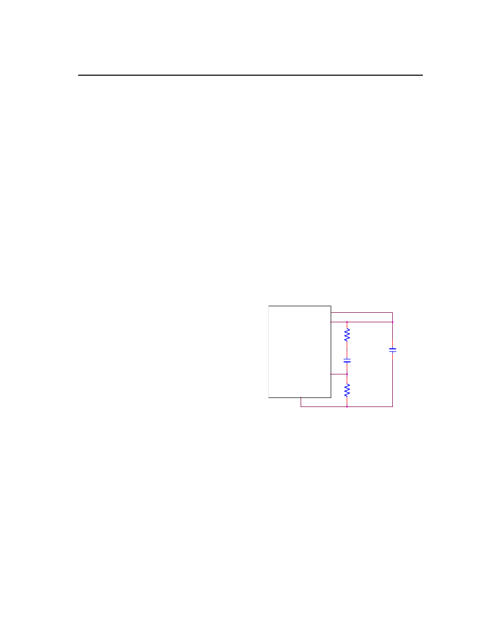
is implemented by connecting a
series R-C between the SENSE and TRIM pins of
the module, as shown in Fig. 34. This R-C allows
the user to externally adjust the voltage loop
feedback compensation of the module.
MODULE
VOUT
SENSE
TRIM
GND
RTUNE
CTUNE
RTrim
C O
Figure. 34. Circuit diagram showing connection
of R
TUME
and C
TUNE
to tune the control loop of
the module.
Recommended values of R
TUNE
and C
TUNE
for
different output capacitor combinations are given in
Tables 2 and 3. Table 2 shows the recommended
values of R
TUNE
and C
TUNE
for different values of
ceramic output capacitors up to 1000uF that might
be needed for an application to meet output ripple
and noise requirements. Selecting R
TUNE
and C
TUNE
according to Table 2 will ensure stable operation of
the module.
In applications with tight output voltage limits in the
presence of dynamic current loading, additional