Data sheet, Input; default outputs: ±54v, General specifications – GE Industrial Solutions CP2725AC54TE User Manual
Page 4: Feature specifications
GE
Data Sheet
CP2725AC54TE CPL High Efficiency Rectifier
100-120/200-277V
AC
input; Default Outputs: ±54V
DC
@ 2725W, 5V
DC
@ 4W
January 30, 2014
©2013 General Electric Company. All rights reserved.
Page 4
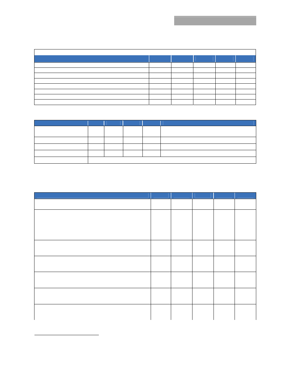
5V
DC
Auxiliary output
Parameter
Symbol
Min
Typ
Max
Unit
Output Voltage Setpoint
V
OUT
5 V
DC
Overall Regulation
-10
7
+5
%
Output Current
0.005
0.75
A
Ripple and Noise (20mHz bandwidth)
50
100
mV
p-p
Over-voltage Clamp
7
V
DC
Over-current
Limit
110 175
%FL
Isolation from the main output STD / POE compliant
500 / 2250
Vdc
Isolation from frame ground
50
Vdc
General Specifications
Parameter
Min
Typ
Max
Units
Notes
Reliability
450,000
Hours
Full load, 25C ; MTBF per SR232 Reliability protection for
electronic equipment, issue 2, method I, case III,
Service Life
10
Years
Full load, excluding fans
Unpacked Weight
2.18/4.8
Kgs/Lbs
Packed Weight
2.45/5.4
Kgs/Lbs
Heat Dissipation
100 Watts or 341 BTUs @ 80% load, 153 Watts or 522 BTUs @ 100% load
Feature Specifications
Unless otherwise indicated, specifications apply over all operating input voltage, resistive load, and temperature conditions. Signals are referenced
to Logic_GRD unless noted otherwise. Fault, PFW, OTW, SMBAlert#, and Power capacity need to be pulled HI through external pull-up resistors. See
Feature Descriptions for additional information.
Parameter
Symbol
Min
Typ
Max
Unit
Enable (should be connected to Logic_GRD) 54V output OFF
V
OUT
1.4
5 V
DC
54V output ON
V
OUT
0
0.8 V
DC
Margining (through adjusting Vcontrol)
44 58
V
DC
Voltage control range
V
control
0
3.3 V
DC
Programmed output voltage range
V
OUT
42 58
V
DC
Voltage adjustment resolution (8-bit A/D)
V
control
3.3 mV
DC
Output configured to 54V
DC
V
control
3.0
3.
3 V
DC
Output configured to 44V
DC
V
control
0
0.1 V
DC
ON/OFF [short pin controls 54V
DC
output - ]
referenced to VOUT( - )
54V output OFF
V
control
1.4
5 V
DC
54V output ON
V
control
0
0.8 V
DC
Module Present [Resistor connected to Logic_GRD internally]
500 Ω
Write protect enabled
V
1
5 V
DC
Write protect disabled
V
0
0.8 V
DC
Over Temperature Warning (OTW) Logic HI (temperature normal)
V
0.7V
DD
12 V
DC
Sink current
I
5 mA
Logic LO (temperature is too high)
V
0
0.4 V
DC
Fault Logic HI (No fault is present)
V
0.7V
DD
12 V
DC
Sink current
I
5 mA
Logic LO (Fault is present)
V
0
0.4 V
DC
SMBAlert# (Alert#_0, Alert#_1) Logic HI (No Alert - normal)
V
0.7V
DD
12 V
DC
Sink current
I
5 mA
Logic LO (Alert is set)
V
0
0.4 V
DC
7
Within ±5% when load is < 0.5A