Data sheet, Front view rear view, Input; default outputs: ±54v – GE Industrial Solutions CP2725AC54TE User Manual
Page 19: Mechanical outline, Output connector, Top view
GE
Data Sheet
CP2725AC54TE CPL High Efficiency Rectifier
100-120/200-277V
AC
input; Default Outputs: ±54V
DC
@ 2725W, 5V
DC
@ 4W
January 30, 2014
©2013 General Electric Company. All rights reserved.
Page 19
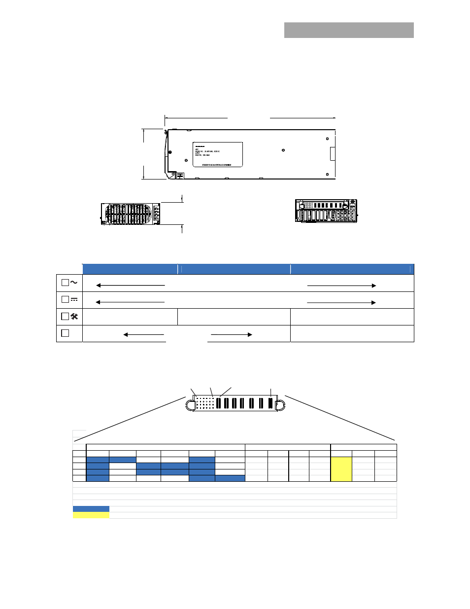
Mechanical Outline
Dimensions
Front Panel LEDs
Analog Mode
I
2
C Mode
RS485 Mode
ON: Input ok
Blinking: Input out of limits
ON: Output ok
Blinking: Overload
ON: Over-temperature Warning
ON: Over-temperature Warning
Blinking: Service
ON: Over-temperature Warning
ON: Fault
Blinking: Not communicating
Output Connector
Mating Connector: right angle PWB mate – all pins: AMP 6450572-1, right angle PWB mate except pass-thru input power: AMP 6450378-1
P1
A6
P7
A1
351.2 mm
(13.85 in)
101.6mm
(4.00 in)
Top View
41.4mm
(1.63 in)
Front View
Rear View
!
6
5
4
3
2
1
A
SCL_0
MOD_PRES
PFW
LOGIC_GRD
RS_485+
UNIT_ADDR
B
SCL_1
OTW
Alert#_0
Alert#_1
RS_485-
8V_INT
C
SDA_0
Margin
Enable
Reset
Ishare
Protocol
D
SDA_1
Fault
5VA
Power_Cap
ON/OFF
SHELF_ADDR
Note: Connector is viewed from the rear positioned inside the rectifier
Signal pins columns 1 and 2 are referenced to V_OUT (–)
Earth
( + )
( + )
P4
V_OUT
Manufacturer part numbers: FCI 51939-568
Last to make-first to break shortest pin
First make-last to break longest pin implemented in the mating connector
SIGNAL
P5
V_OUT
Signal pins columns 3 through 6 are referenced to Logic GRD
P6
V_OUT
( - )
P7
(Neutral)
P3
INPUT POWER
OUTPUT POWER
EARTH
P1
LINE-1
(HOT)
(GND)
( - )
V_OUT
P2
LINE-2
ON: Fault