Data sheet, Input; default outputs: ±54v, Absolute maximum ratings – GE Industrial Solutions CP2725AC54TE User Manual
Page 2: Electrical specifications
GE
Data Sheet
CP2725AC54TE CPL High Efficiency Rectifier
100-120/200-277V
AC
input; Default Outputs: ±54V
DC
@ 2725W, 5V
DC
@ 4W
January 30, 2014
©2013 General Electric Company. All rights reserved.
Page 2
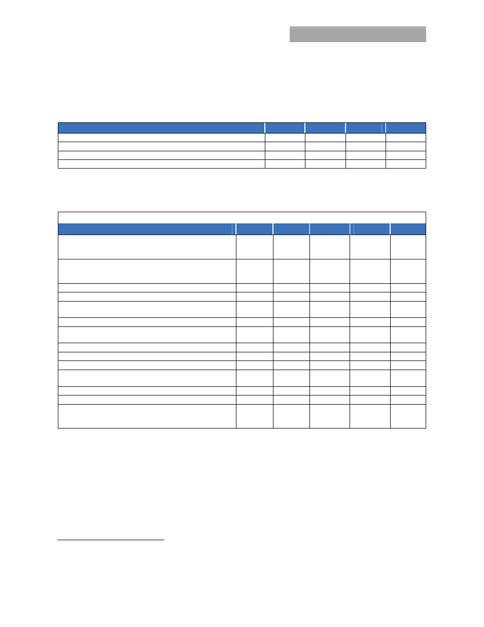
Absolute Maximum Ratings
Stresses in excess of the absolute maximum ratings can cause permanent damage to the device. These are absolute stress ratings
only, functional operation of the device is not implied at these or any other conditions in excess of those given in the operations
sections of the data sheet. Exposure to absolute maximum ratings for extended periods can adversely affect the device reliability.
Parameter
Symbol
Min
Max
Unit
Input Voltage: Continuous
VIN
0
300
V
AC
Operating Ambient Temperature
TA
-10
75
1
°C
Storage Temperature
Tstg
-40
85
°C
I/O Isolation voltage to Frame (100% factory Hi-Pot tested)
1500
V
AC
Electrical Specifications
Unless otherwise indicated, specifications apply over all operating input voltage, Vo=54V
DC
, resistive load, and temperature
conditions.
INPUT
Parameter
Symbol
Min
Typ
Max
Unit
Startup Input Voltage
Low-line Operation
High-line Operation
V
IN
90
185
V
AC
Operating Voltage Range
Low-line Configuration
High-line Configuration
V
IN
90
185
100 – 120
200 - 277
140
300
V
AC
Input Voltage Swell (no damage)
305
Input Frequency
F
IN
47 66
Hz
Input Current; at 110V
AC
at 240V
AC
I
IN
11.9
13.1
A
AC
Inrush Transient (at 25°C, excluding X-Capacitor charging)
I
IN
25 30
A
PK
Idle Power (at 220V
AC
) 54V OFF
54V ON @ Io=0
P
IN
8.2
16
W
Input Leakage Current (265V
AC
, 60Hz)
I
IN
2.5 3.5
mA
Power Factor (50 – 100% load)
PF
0.96 0.995
Efficiency
2
(30 – 80% of FL, 240V
AC
@ 25C)
94.5 96.2
%
Holdup time (output allowed to decay down to 40V
DC
)
For loads below 1200W
T
20
30
ms
Ride thru (tested at 115V @ 230V. (Complies to CISPR24)
T
1/2
1
cycle
Power Fail Warning
3
(main output allowed to decay to 40V
DC
)
PFW 3
5
ms
Isolation (per EN60950) (
consult factory for testing to this requirement)
Input-Chassis/Signals
Input - Output
V
1500
3000
V
AC
V
AC
1
Derated above 50C at 2.5%/C
2
See efficiency curve in the Characteristics Curves section.
3
Internal protection circuits may override the PFW signal and may trigger an immediate shutdown.