Data sheet, Input; default outputs: ±54v, Electrical specifications (continued) – GE Industrial Solutions CP2725AC54TE User Manual
Page 3
GE
Data Sheet
CP2725AC54TE CPL High Efficiency Rectifier
100-120/200-277V
AC
input; Default Outputs: ±54V
DC
@ 2725W, 5V
DC
@ 4W
January 30, 2014
©2013 General Electric Company. All rights reserved.
Page 3
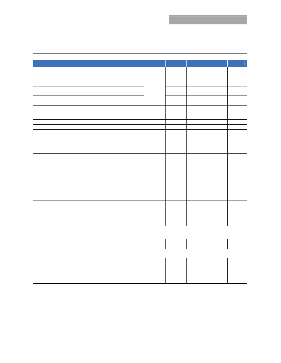
Electrical Specifications (continued)
54V
DC
MAIN OUTPUT
Parameter
Symbol
Min
Typ
Max
Unit
Output Power @ low line input 100 – 120V
AC
@ high line input 200 – 277V
AC
@ nominal 277Vac and T
amb
> 45C
W
1200
2725
2000
W
DC
Default Set point
V
OUT
54
V
DC
Overall regulation (load, temperature, aging) 0 - 45C LOAD > 2.5A
> 45C
-1
-2
+1
+2
%
Output Voltage Set Range - analog margining
- Set either by I
2
C or RS485
44
42
58
58
V
DC
Output Current - @ 1200W (100 – 120Vac), 54V/52V
@ 2725W (200 – 240V
AC
), 54V/52V
@ 2000W ( > 277V
AC
@ Tamb > 45C), 54V/52V
I
Out
1
1
1
25/23
50.5/52.4
37/38.4
A
DC
Current Share ( > 50% FL)
-5 5
%FL
Proportional Current Share between different rectifiers ( > 50% FL)
<7
%FL
Output Ripple ( 20MHz bandwidth, load > 1A)
RMS (5Hz to 20MHz)
Peak-to-Peak (5Hz to 20MHz)
Psophometric Noise
V
OUT
100
300
4
9
5
mV
rms
mV
p-p
mV
rms
External Bulk Load Capacitance
C
OUT
0
5,000
F
Turn-On (monotonic turn-ON from 30 – 100% of Vnom above 5C)
Delay
Rise Time – PMBus mode
Rise Time - RS-485 mode
6
Output Overshoot
T
V
OUT
5
100
5
2
s
ms
s
%
Load Step Response ( I
O,START
> 2.5A )
I
V, V
AC
285
AC
V, V
AC
≥ 285
AC
Response Time
I
OUT
V
OUT
V
OUT
T
2.0
3.2
2
50
%FL
V
DC
V
DC
ms
Overload - Power limit @ high line down to 52V
DC
Power limit @ low line down to 52V
DC
High line current limit if V
out
> 41.5V
DC
High line current limit if V
out
< 41.5V
DC
Low line current limit
Output shutdown (commences as voltage decays below this level)
P
OUT
P
OUT
I
OUT
V
OUT
2725
1200
53
36
26
39
W
DC
W
DC
A
DC
A
DC
A
DC
V
DC
System power up
Upon insertion the power supply will delay an overload shutdown
for 20 seconds allowing for the insertion and startup of multiple
modules within a system.
Overvoltage - 200ms delayed shutdown
Immediate shutdown
V
OUT
> 65
< 65
V
DC
Latched shutdown
Three restart attempts are implemented within a 1 minute window
prior to a latched shutdown.
Over-temperature warning (prior to commencement of shutdown)
Shutdown (below the max device rating being protected)
Restart attempt Hysteresis (below shutdown level)
T
5
20
10
C
Isolation Output-Chassis (Standard, non-POE compliant)
Output-Chassis/Signals (POE compliant per IEEE802.3)
V
500
2250
V
DC
V
DC
4
500mVp-p max above 280V
AC
input
or above 56Vdc output;
5
Complies with ANSI TI.523-2001 section 4.9.2 emissions max limit of 20mV flat unweighted wideband noise limits
6
Below -5°C, the rise time is approximately 5 minutes to protect the bulk capacitors.