Cr 194 one/two-high vacuum limitamp, Ar control page 19, Ge limitamp – GE Industrial Solutions Limitamp AR User Manual
Page 19: Ar medium voltage motor control enclosures
CR 194 One/Two-High Vacuum Limitamp
®
AR Control
Page 19
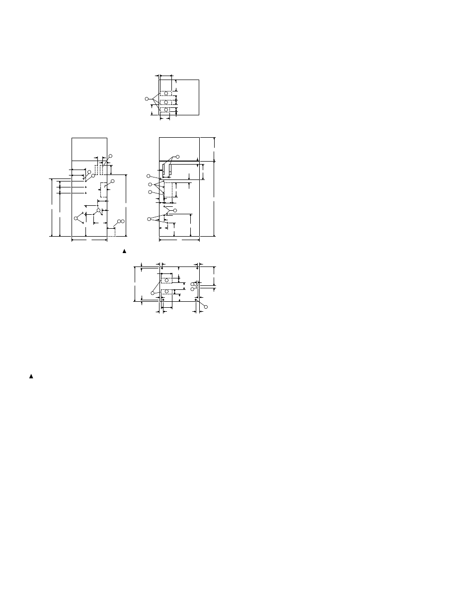
CR194 AR 800A, Stationary or Draw-out,
Outline Dimensions, One-High, Top/Bottom Cable Entry.
9
4
8-7/16
6
6
L3
L2
L1
E
68-4/5
P
M
10-1/2
2-9/16
6
14
TOP VIEW
FRONT
2-1/2
K
P
D
B1
M
N
K
6
7-9/16
6
14-3/16
1-1/2
42
3/4
2
10-1/2
2-5/16
10-1/2
FRONT
26
3
1-5/16
2
14
J
K
52
6-1/2
6-1/2
L1
L2
L3
12-1/2
10
11-1/2
6
17
26
10-1/2
T1
T2
T3
D
72
5-1/2
6-1/2
42
10-5/8
5-3/4
12-3/4
4-3/16
C
T2
T1,T3
6
90
X
C
F
48
B
X
48
17-5/8
13-1/2
- 1800 LBS.
H
1-1/2
FRONT
3-1/2
6
G
F
E
16-3/4
27-3/4
9
*
7
PLENUM
24
4-1/2
2-3/4
- 816 KG.
8-7/16
N
7-9/16
Enclosure Outline dimensions 2400-7200 Volts
CR194 AR 800A, 1-High, 48" Wide
GE Limitamp
®
AR Medium Voltage Motor Control
Enclosures
E10
REV: 01
FRONT VIEW
FLOOR PLAN
L.H.SIDE VIEW
Notes:
B — Incoming Power Terminal Connection
B1 — AC Power Bus, 800A
C — Control Lead Terminal Board
D — Motor Lead Terminal Connection
E — Ground Bus Terminal Connection
F — Ground Bus Terminal Connection
(If Ordered)
G — Space Required to Open Doors 90°
H
Four-Foot Aisle for contactor removal
J
—
Mounting Holes for 1/2" Diameter Anchor Bolts
K
—
Space Available for Incoming Conduit
M
—
Recommended Position for Incoming Motor Conduit
N
—
Recommended Position for Incoming Control Conduit
P
—
Recommended Position for Incoming Power Conduit
X
—
— LV Box
* — Indicates Terminal Location - Approximate for Cable Length
— Approximate Weight
Figure 40. Top/Bottom Cable Entry 800A