Cr 194 one/two-high vacuum limitamp, Ar control page 17, Ge limitamp – GE Industrial Solutions Limitamp AR User Manual
Page 17: Ar medium voltage motor control enclosures
CR 194 One/Two-High Vacuum Limitamp
®
AR Control
Page 17
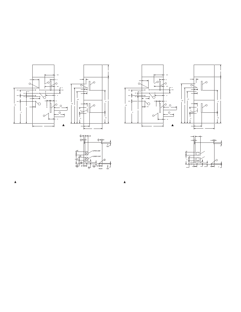
CR194 AR 400A, Stationary or Draw-out,
Outline Dimensions, Two-High, Bottom Cable Entry.
PLENUM
FRONT VIEW
FLOOR PLAN
L.H.SIDE VIEW
C
11 3
16
1914
1134
613
16
C
C
2015
16
4314
4 9
16
611
16
7 1
16
6115
16
69
7613
16
712
6813
16
52
612
612
14 3
16
1213
16
E
B1
L3
L2
L1
D
PLENUM
D
D
18 3
16
18 1
16
1612
32
G
2-HI
LOWER UNIT
UPPER UNIT
36
42
D
BTM CABLE ENTRY
-2200 lbs
998 Kg
FRONT
90
24
C
612
Enclosure Outline dimensions 2400-7200 Volts
CR194 AR 400A, 2 High, 36" Wide
(Stationary or Draw-out)-BTM CABLE ENTRY
GE Limitamp
®
AR Medium Voltage Motor Control
Enclosures
Notes:
B1 — AC Power Bus, 1200A
B2 — AC Power Bus, 3000A
C — Control Lead Terminal Board
D — Motor Lead Terminal Connection
E — Ground Bus Terminal Connection
G — Space Required to Open Doors 135°
H — Four-foot Aisle for Contactor Removal
J — Mounting Holes for 1/2" Diameter
Anchor Bolts
M — Recommended Position for Incoming
Motor Conduit
N — Recommended Position for Incoming Control Conduit
* — Indicates Terminal Location - Approximate for Cable Length
— Approximate Weight
E4
1034
*
H
48
REV: 01
T1
T2
T3
T1
T2
T3
T1
T2
T3
T1-T3
T2
*
*
* *
*
*
*
*
*
*
513
16
B2
L2
L3
11
L1
11
4278
712
E4
PLENUM
FRONT VIEW
L.H.SIDE VIEW
M
M
613
16
1738
258
10
6
6
LOWER UNIT
UPPER UNIT
N
FLOOR PLAN
212 2 5
16
3
4
TYP.
6
6
2
TYP.
112
C
15 3
16
1914
1134
613
16
C
C
2015
16
4314
4 9
16
611
16
7 1
16
6115
16
69
7613
16
712
6813
16
52
612
612
14 3
16
1213
16
E
B1
D
PLENUM
D
D
18 3
16
18 1
16
1612
FRONT
36
G
2-HI
LOWER UNIT
UPPER UNIT
40
42
D
BTM CABLE ENTRY
-2450 lbs
1112 Kg
FRONT
112
90
24
C
612
Enclosure Outline dimensions 2400-7200 Volts
CR194 AR 400A, 2 High, 40" Wide
(Stationary or Draw-out)-BTM CABLE ENTRY
J
E5
GE Limitamp
®
AR Medium Voltage Motor Control
Enclosures
H
48
REV: 01
T1
T2
T3
T1
T3
T1
T2
T3
T1-T3
T2
*
*
*
* *
*
*
*
*
*
4278
513
16
B2
L1
11
11
L3
L2
L1
L2
L3
712
T2
*
1034
Notes:
B1 — AC Power Bus, 1200A
B2 — AC Power Bus, 3000A
C — Control Lead Terminal Board
D — Motor Lead Terminal Connection
E — Ground Bus Terminal Connection
G — Space Required to Open Doors 135°
H — Four-foot Aisle for Contactor Removal
J — Mounting Holes for 1/2" Diameter
Anchor Bolts
M — Recommended Position for Incoming
Motor Conduit
N — Recommended Position for Incoming Control Conduit
* — Indicates Terminal Location - Approximate for Cable Length
— Approximate Weight
Figure 38. Bottom Cable Entry 400A