GE Industrial Solutions Limitamp AR User Manual
Page 10
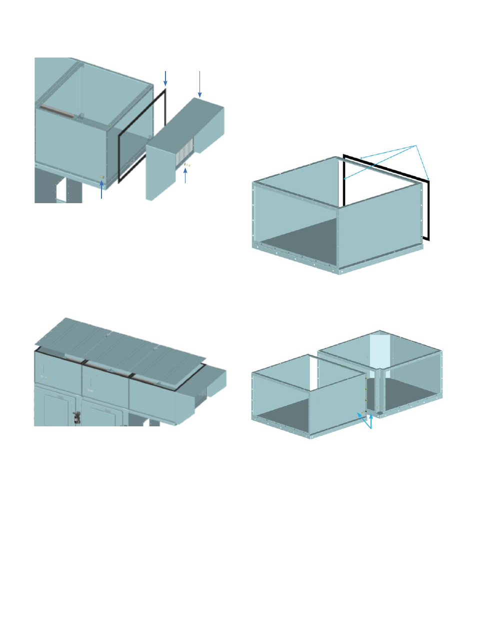
Step 11: Continue the assembly of extension plenums following
the same procedure. At the end of the extension plenum the
end duct assembly must be installed.
Figure 23. Assembly of end duct to the last segment
of the plenum.
Figure 24. Mount top covers using 3/8” diameter bolts.
Sealer
3/8” Hardware
End Duct
3/8” Hardware
If customer chooses to install their own version of end duct
segment then the duct must allow a minimum open exhaust
area of 428 in
2
.
Step 12: Once all the plenums are in place and bolted together
apply gasket around the perimeter of each plenum frame and
mount the cover plates using 3/8” hardware.
CR 194 One/Two-High Vacuum Limitamp
®
AR Control
Page 10
Turned Extension Plenum Installation
Guide (Front/Rear)
At the installation site, remove all separately packaged
components shipped within the Limitamp AR unit. Find the
Turned Plenum, mounting hardware and place them in the
work area.
Step 1: Remove top cover plate on existing extension plenum
for assembly. Apply sealer around perimeter of existing
extension plenum side flanges, where turned plenum (Front/
Rear) will be attached.
Sealer
Figure 25. How to apply sealer around perimeter of plenum.
Step 2: Install 3/8” diameter mounting bolts to attach turned
plenum (Front/Rear) to the extension plenum.
Figure 26. Use 3/8” hardware to mount turned plenum
(Front/Rear).
3/8” Hardware