SENA ProBee-ZE20S-HAOL User Manual
Page 40
ProBee-ZE20S-HAxx User Guide Rev 1.9
40
illumination and analog input is as follows:
Illumination(Lux) = Volt(mV) * 0.25(Lux/mV)
Note: The LED On/Off switch (SW20) should be placed to LED_OFF.
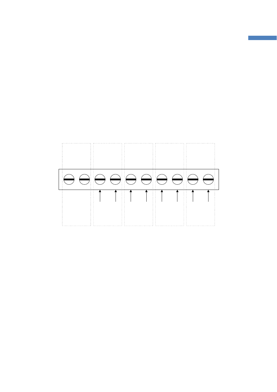
5.3.10 Terminal Block
The development board has a terminal block for external analog inputs. Figure 5-2 shows the layout of
the terminal block. To use external analog inputs instead of the variable resistors, temperature sensor or
light sensor, the ADC_0 (SW4), ADC_1 (SW5), ADC_2 (SW6) or ADC_3 (SW7) should be placed on
EXT_0, EXT_1, EXT_2, or EXT_3.
Reserved
ADC_3
ADC_0
ADC_2
ADC_1
GND
AI0
GND
AI1
GND
AI3
GND
AI2
Figure 5-2 Terminal Block for External Anlalog Inputs
Note: The LED On/Off switch (SW20) should be placed to LED_OFF.
5.4
Configuration Example: 1 Coordinator and 2 End-Devices
Here is another example assuming different system configurations. This example can be described as
follows:
One ZE20S module acts as a ProBeeHACI coordinator and it is connected to a host computer via
USB cable.
One ZE20S module acts as a ProBeeHADL end device and it receives control commands from
the coordinator.
One ZE20S module acts as a ProBeeHAOL end device and it receives control commands from
the coordinator.