Installation instructions (continued) – S&B Filters Intake Elbow 6-1007 User Manual
Page 2
15461 Slover Ave., Fontana, CA 92337 - Phone: (909) 947-0015 - Fax: (909) 947-0603 -
INSTALLATION INSTRUCTIONS (Continued)
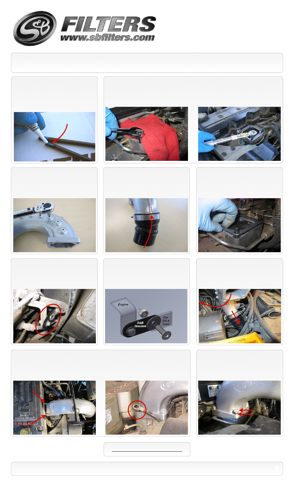
9.
Remove the studs and place a small
amount of the supplied Thread Locker
(N)
to
the correct size Studs
(J or H)
and thread the
studs by hand into the two bolt holes farthest
from the valve cover. Stage the Socket Cap
Screws
(E)
by applying Thread Locker also.
10.
Double nut a stud using the supplied Jam Nuts
(K)
. Turning only the top nut, torque the stud to
40 In. lbs. Remove the Jam nuts and repeat process on the other stud then discard the Jam nuts.
Note: You should first place a clean shop towel in the opening of the intake manifold to prevent any
debris from falling inside.
13.
Place the other supplied Graphite
Gasket
(I)
over the Studs on top of the heater
grid block.
SEE EXPLODED VIEW ON PAGE 4
2
P/N: 76-1007
14.
Remove the bolt at the lower dip stick
tube bracket. Place the Dip Stick Bracket
(O)
(oval hole) in its place and secure loosely with
the OE bolt.
Short threaded end
15.
Place the M6 Bolt
(P)
through the dip
stick tube bracket and the S&B bracket
(O)
and thread the M6 lock nut
(Q)
on the bolt,
leave loose until the upper mount is in place.
11.
Apply a thread sealant such as Teflon
tape to each 1/8” NPT plug
(G)
and insert the
plugs into the ports you will not be using on
the S&B elbow. Use a 3/16 hex socket and
tighten, do not exceed 40 In. lbs.
12.
Install the large end of the Silicone
hump coupler
(S)
over the end of the Elbow
(F)
and slide the supplied T-bolt clamp
(R)
over the hump coupler. Leave clamp loose
for now.
16.
Slide the OE t-bolt clamp down the
intercooler tube. Push the silicone end of the
elbow assembly down over the intercooler
tube. Then rotate the elbow assembly over
the studs on the heater grid.
17.
Install the two M8 Socket head screws
(E)
and M8 washers
(D)
through the two holes. Hand
tighten for now. If there was a ground wire connected to the elbow, place it back in the same location
between the washer and the flange of the elbow.
18.
Place a M8 washer
(D)
over each stud
and thread on the M8 lock nuts
(C)
. Torque
both the lock nuts and the screws to 145 In.
lbs. If you use a crow foot to torque the nuts,
see the crow foot calculation on page 3.