Ups/inverters, Options – Powersolve C(AC) Series User Manual
Page 6
www.powersolve.co.uk
Powersolve Electronics Ltd. 8A, Arnhem Road, Newbury, RG14 5RU. England
Tel:01635 521858 Fax: 01635 523771 Email: [email protected]
F
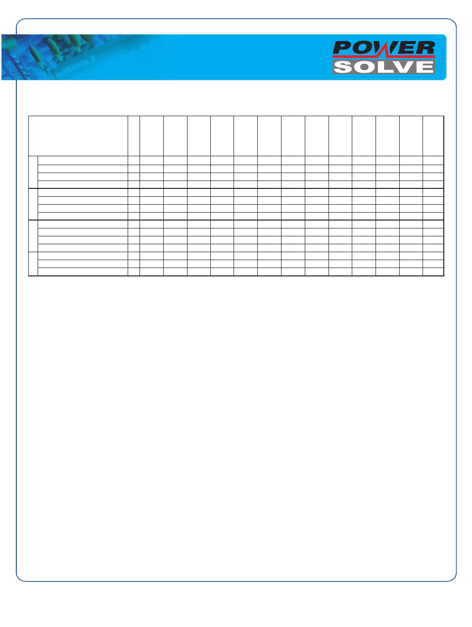
Options
Tropical protection
T
•
•
•
•
•
•
•
•
•
•
•
•
•
Extended temp. range
C
•
•
•
•
•
•
•
•
•
•
•
•
•
Increased mech. strength
MS
•
•
•
•
•
•
•
•
•
•
•
•
•
Wall mounting
W
•
•
•
•
•
•
•
•
•
•
•
•
•
Inrush current limiting
(1)
I
•
*
*
*
*
*
*
*
•
•
*
*
*
Series diode
SD
*
*
*
*
*
*
*
*
*
*
*
*
*
Anti-parallel diode
AD
*
*
*
*
*
*
*
*
*
*
*
*
*
Autoranging
AU
*
*
*
*
*
*
*
*
*
*
Decoupling diode
DD
*
*
*
*
*
*
*
*
*
*
*
*
*
Active current sharing
CS
*
*
•
•
•
•
•
•
•
•
•
Inhibit (to be specified)
H
*
*
*
*
•
•
•
•
•
•
•
•
•
Externally programmable
E
*
*
*
*
*
*
*
*
*
*
*
*
*
Power fail
P
•
•
•
•
•
•
•
•
•
•
•
•
•
DC-OK one output
D
•
•
•
•
•
•
•
•
•
•
•
•
•
Signals with relay
R
*
*
*
*
*
*
*
*
•
•
•
•
•
C4700
C4800
C5600
C5700
C5800
C3700
C3600
C3500
C1300
C1500
C500
C600
C300
Designation
Mech
Input
Output
Signals
Options
Option T (Tropical protection):
The unit is given additional protection by a heavy coat of varnish on the
printed circuit board(s) and components.
Option C (Extended temperature range):
Units are designed & tested for operation at an ambient temperature down
to -40 ºC.
Option MS (Increased mechanical strength):
Screws are fastened by Locktite and heavy components are fastened by
ties or glue to following specification.
Vibration: 2 – 2000 Hz at 2 G,
Shock: 10 G for 11 ms to DIN 40046 part 7.
Option W (Wall mounting):
Module is screwed to a mounting plate for installation within a cabinet).
Option I (Inrush current limiting):
A thermistor is connected in series with the input lines which changes its
resistance from high to low when it gets hot. It does not reduce the
current surge if the input power is interrupted for a short period of time not
allowing the thermistor to cool down. Electronic inrush current limiting
device is available upon request.
Option SD (Series diode):
A series diode is connected on the input of the module to protect the unit
from reverse input polarity connection.
Option AD (Parallel diode):
A diode is provided in parallel to the input. Should the input to the
module be reverse-connected, the input fuse (either internal or external
fuse) will blow, protecting the unit.
Option DD (Decoupling diode):
For redundant operation the outputs of two or more units are paralleled
behind de-coupling diodes so that an internal fault of one module does not
affect the operation of the others. These diodes cause power losses. For
high currents the de-coupling diode may have to be installed
externally.
Option SD, AD & DD:
May need to be fitted externally - contact sales office.
Option CS (Active current sharing):
By means of an additional control circuit active current sharing is provided
via an interconnecting wire between 2 or more units.
Option AU (Auto-ranging):
In standard dual AC input units (115/230 VAC) the range is selected by
connecting the input line to different pins on the connector. With auto-
ranging the unit senses the input voltage and automatically provides the
correct connection.
Option H (Inhibit):
Operation of the unit is inhibited if a voltage signal (5 V/10 mA) is applied in
reference to the negative line of the (main) output. Alternatively, a
connector pin connected to the negative input line also shuts off the
converter (to be specified). This can also be used in conjunction with a
thermal trip which shuts unit down.
Option E (Programmable by ext. signal):
An ext. signal applied with reference to the negative output line programs
the output voltage.
Option P (Power fail):
A signal (logic or relay) is given if the input voltage drops below the
specified limit. In AC input units we sense the rectified input voltage so that
a power fail alarm can be avoided if at light load mains power returns
before the input capacitors are substantially discharged.
Option D (DC-OK, one output):
A signal (logic or relay) is given if the voltage of the main output is below
the specified limit. In multi-output systems the main output is monitored.
Option M (DC-OK, all outputs):
In multi-output systems a signal is provided if the voltage of any output is
below the specified limit.
Option AC (AC-OK)
A logic signal is given if the output voltage of an inverter is below the
specified limit.
Option R (Relay):
Options P, D and M are available in conjunction with option R. A relay is
provided for indication instead of a logic signal with a N.O., N.C. or
changeover contact (to be specified).
Option ‘Y’ (Sys-reset):
This logic signal is a combination of power fail and DC-OK as specified for
VME systems.
Notes:
1. Standard for mains input modelto Series C3700.
•
Option is available in combination with other options.
*
Option is available with certain restrictions - contact Sales Office.
UPS/INVERTERS