Powersolve HSEUIreg04801 Series User Manual
Page 5
Powersolve Electronics Ltd., Unit 8A Arnhem Road, Newbury RG14 5RU, United Kingdom
Tel 0044 (0)1635 521858 Fax 0044 (0)1635 523771
www.powersolve.co.uk
p.5/9 05.12D
(Subject to alterations. This product is not designed to be used in applications such as life support systems wherein a failure or malfunction could result in injury or death)
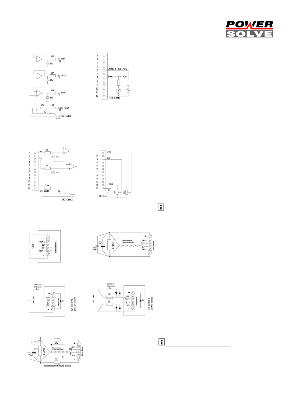
Monitor Outputs SCM (fig.1)
Monitor Output Connections (fig.2)
Program Inputs SCM (fig.3)
Program Input Connections (fig.4)
(example with external poti)
Local Sensing (fig.5)
Remote Sensing (fig.6)
Battery Charger Mode (fig.7)
External Sense Protection (fig.8)
Maximum Sense Compensation (fig.9)
Monitor Outputs
The monitor outputs are buffered with OP-amplifiers, pre-
resistors & parallel connected zener diodes (fig.1). The
monitor outs can be selected between +5Vdc or +10Vdc
control voltage. The signal is absolute proportional to the
adjusted output voltage and current. The monitor outputs
are non-floating. Connections see figure 2.
Programmable Inputs
The output voltage and the output current are
programmed with an analogue signal. The input signal is
selectable between 0-5Vdc, 0-10Vdc, 0-20mA or 4-20mA
with a front sided DIP-switcher. The response is very
exact and. The output response behaves linear to the
control signal.
The inputs are protected with internal pre-resistors,
zener diodes and capacitors (fig.3). The capacitor limits
the slew rate, accurately. The program inputs are non-
floating. The monitor GND is connected to the negative
pole of the main outputs. An incorrect connection triggers
an internal PTC fuse. Unlocking the incorrect connection
resets this fuse to being recovered (auto recovery).
External potentiometer control mode (fig.4)
The USEUIreg features an internal reference voltage of
Uref = 5,2Vdc or 10,4Vdc, selected with the DIP-switch.
An external pre-resistor or a potentiometer of 10k can be
connected to adjust the output voltage and current.
Sense Mode
The HSEUIreg provides sensing connections to
compensate voltage drop down from wire system. The
maximum compensation is 2V (fig.9). Be aware that this
operation mode may recommend extended preparations
concerning interference elimination or other protections. It
should
be
set
by
the
advanced
user.
Non-sense mode recommends the S +/- connected to
AUX +/- with very short wires = Local Sensing (fig.5)
Remote Sensing (2V per lead load, fig6)
Disconnect local sensing wires (fig.1) from the AUX +/-
and the S +/- connections. Connect the sense lines to the
load. Be sure that +/- connections are matching!
To basically prevent from interferences enable to twist
sense compensation lines. To reduce inductive influences
make sure that load wires are installed closely each
other. Driving a pulsative load requires a large electrolytic
and a ceramic capacitor being connected (see fig.6 C1 &
C2). Make sure that C1 & C2 are not oscillating with load
wires. This would cause ripple voltage into the lines. The
internal over voltage protection (OVP) controls the output
voltage directly at the output connectors. It opens
automatically in case of failure from the source (p.6 fig.4).
Battery Charger Mode (fig.7)
The HSEUIreg is the perfect a battery charger. It can be
used as constant voltage (CV) or constant current
charger (CC). As a stand-alone solution the HSEUIreg
features constant charging with automatic over charging
protection. Used with an external control unit (PLC) the
HSEUIreg charges any battery backup application you
need to install, at very low investment cost with a perfect
control and system compatibility from the PLC.
We advise to use a circuit breaker to prevent from
disconnections. Use fast Z-types with the double battery
dc-voltage capability, like being used for semiconductor
protection.
Remote Sensing with battery charger
Using the HSEUIreg as a battery charger, avoid remote
sensing operation mode. It may cause serious damage to
the unit when the battery connections are being mixed
up. If you really need to install Remote Sensing apply to
the figure 8 circuit. Good values are 250mA for Si fuses
and 3…5A capability for the diodes.